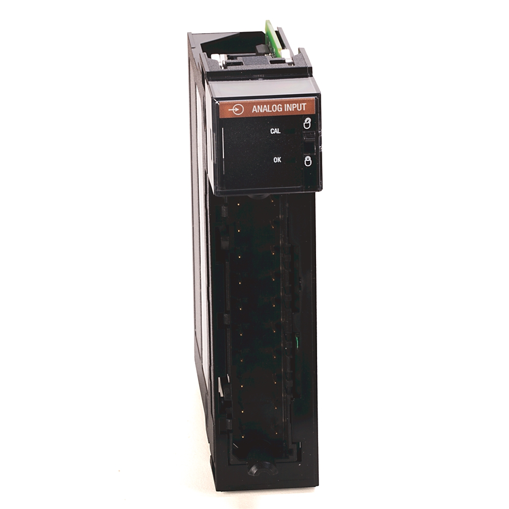
ControlLogix 6 Point Isolated A/I Module
| Unique Product Identifier |
1756-if6i
|
|---|---|
| UPC |
612598164646
|
| Estimated Lead Time |
1 day
|
| Standard Warranty Duration |
1 year See details |
| Country of Origin |
United States of America
|
| EU Importer Address |
Rockwell Automation N.V |
| EU Authorized Representative Address |
Rockwell Automation N.V |
The information provided by Rockwell Automation on www.rockwellautomation.com (the “Site”) is for demonstration purposes only and may be incomplete or inaccurate. All information is provided “as is”, and Rockwell Automation makes no representations or warranties of any kind, express or implied, regarding the accuracy, adequacy, validity, reliability, or completeness of any information on the Site. Use of this information is at your own risk.
| Display |
Module Health, In Calibration,Mode
|
|---|---|
| Input Signal |
+/- 10V, 0-10.5V, 0-5.25V,0-21mA
|
| Isolation |
250 V continuous between,inputs
|
| Number Of Channels |
6
|
| Special Features |
Per Point Isolation
|
| Input, current |
True
|
|---|---|
| Input, voltage |
True
|
| Input, resistor |
False
|
| Input, resistance thermometer |
False
|
| Input, thermocouple |
False
|
| Input signal, configurable |
True
|
| Output, current |
False
|
| Output, voltage |
False
|
| Output signal configurable |
False
|
| Analogue inputs configurable |
True
|
| Analogue outputs configurable |
False
|
| Type of electric connection |
Screw-/spring clA connection
|
| Channel bandwidth |
15 Hz
|
| Module keying |
Electronic, software configurable
|
| Module conversion method |
Sigma-Delta
|
| Offset drift |
2 µV/°C
|
| Input range |
±10.5V @ 0...10.5V, 0...5.25V @ 0...21mA
|
| Data format |
Integer mode (left justified, 2 s complement) IEEE 32-bit floating point
|
| Wire category |
Category: 2
|
| Overvoltage protection |
Voltage: 120V AC/DC maximum, Current: 8V AC/DC (with onboard current resistor), maximum
|
| Common mode noise rejection |
120 dB @ 60 Hz, 100 dB @ 50 Hz
|
| Normal mode noise rejection |
60 dB @ 60 Hz
|
| Module error |
0.54% of range
|
| Gain drift with temperature |
Voltage: 35 ppm/°C, 80 ppm/°C maximum, Current: 45 ppm/°C, 90 ppm/°C maximum
|
| Module input scan time, min |
25 ms minimum - floating point, 10 ms minimum - integer
|
| Settling time |
<80 ms to 5% of full scale
|
| Total backplane power |
3.7 W
|
| Thermal dissipation |
Voltage: 12.62 BTU/hr, Current: 14.32 BTU/hr
|
| Current draw |
250mA @ 5.1V, 100mA @ 24V
|
| Inputs |
6 individually isolated
|
| Power dissipation |
Voltage: 3.7 W, maximum, Current: 4.3 W, maximum
|
| Resolution |
16 bit, 10.5V: 343 µV/bit, 0...10.5V: 171 µV/bit, 0...5.25V: 86 µV/bit, 0...21 mA: 0.34 µA/bit
|
| Calibrated accuracy |
Better than 0.1% of range @ 25 °C (77 °F)
|
| Open circuit detection time |
Positive full scale reading within 5 s
|
| Suitable for safety functions |
False
|
| Onboard data alarming |
True
|
| Scaling to engineering units |
True
|
| Real-time channel sampling |
True
|
| Surrounding air temperature, max |
60 °C
|
|---|---|
| North American temperature code |
T4A
|
| Operating temperature |
0 °C
|
| Emissions |
IEC 61000-6-4
|
| ESD immunity |
6 kV contact discharges, 8 kV air discharges
|
| EFT/B immunity |
±2kV @ 5kHz on shielded signal ports
|
| Relative humidity |
5...95% noncondensing
|
| Conducted RF immunity |
10V rms with 1 kHz sine wave 80% AM from 150 kHz...80 MHz on shielded signal ports
|
| Surge transient immunity |
±2 kV line-earth (CM) on shielded signal ports
|
| Radiated RF immunity |
10 V/m with 1 kHz sine-wave 80% AM from 80...2000 MHz, 10 V/m with 200 Hz 50% pulse 100% AM @ 900 MHz, 10 V/m with 200 Hz 50% pulse 100% AM @ 1890 MHz, 3 V/m with 1 kHz sine-wave 80% AM from 2000...2700 MHz
|
| Nonoperating temperature |
-40 °C
|
| RTB keying |
User-defined mechanical
|
|---|---|
| Vibration |
2 G @ 10...500 Hz
|
| Shock |
Operating: 30 G, Nonoperating: 30 G
|
| Slot width |
1
|
| Input impedance |
Voltage: >10 MΩ, Current: 249 Ω
|
|---|
| Isolation voltage |
250V (continuous), basic insulation type, input channels-to-backplane, and input channel-to-channel Routine tested at 1350V AC @ 2s
|
|---|
| Enclosure type rating |
None (open-style)
|
|---|
| Drawings | |
|---|---|
| 3-Dimensional STEP model (STP) | Download (ZIP) |
| Product Drawing | Drawing (DWG) |
| Product Drawing | Drawing (DWG) |
| Product Drawing | Drawing (DXF) |
| Product Drawing | Drawing (DWG) |
| Product Drawing | Drawing (DWG) |
| Drawings |
|---|
| 3-Dimensional STEP model (STP) Download (ZIP) |
| Product Drawing Drawing (DWG) |
| Product Drawing Drawing (DWG) |
| Product Drawing Drawing (DXF) |
| Product Drawing Drawing (DWG) |
| Product Drawing Drawing (DWG) |
| General | Publication |
|---|---|
| Selection Guide | 1756-SG001 |
| Product Profile | -- |
| Technical Detail | -- |
| Product Cutsheet | -- |
| Technical Data | Publication |
|---|---|
| 1756-td002_-en-e | 1756-TD002 |
- Firmware for 1756-IF6I Analog I/O
- EDS files for 1756-IF6I (multi)
- EDS files for ControlLogix Family (multi)
- Safety
- ATEX
This product was certified with the above certifications as of {}. Products sold before or after this date might carry different certifications. Please review the product label to check for the certifications your specific product carries.
| Technotes |
|---|
Overview
| Unique Product Identifier |
1756-if6i
|
|---|---|
| UPC |
612598164646
|
| Estimated Lead Time |
1 day
|
| Standard Warranty Duration |
1 year See details |
| Country of Origin |
United States of America
|
| EU Importer Address |
Rockwell Automation N.V |
| EU Authorized Representative Address |
Rockwell Automation N.V |
The information provided by Rockwell Automation on www.rockwellautomation.com (the “Site”) is for demonstration purposes only and may be incomplete or inaccurate. All information is provided “as is”, and Rockwell Automation makes no representations or warranties of any kind, express or implied, regarding the accuracy, adequacy, validity, reliability, or completeness of any information on the Site. Use of this information is at your own risk.
Technical Specifications
| Display |
Module Health, In Calibration,Mode
|
|---|---|
| Input Signal |
+/- 10V, 0-10.5V, 0-5.25V,0-21mA
|
| Isolation |
250 V continuous between,inputs
|
| Number Of Channels |
6
|
| Special Features |
Per Point Isolation
|
| Input, current |
True
|
|---|---|
| Input, voltage |
True
|
| Input, resistor |
False
|
| Input, resistance thermometer |
False
|
| Input, thermocouple |
False
|
| Input signal, configurable |
True
|
| Output, current |
False
|
| Output, voltage |
False
|
| Output signal configurable |
False
|
| Analogue inputs configurable |
True
|
| Analogue outputs configurable |
False
|
| Type of electric connection |
Screw-/spring clA connection
|
| Channel bandwidth |
15 Hz
|
| Module keying |
Electronic, software configurable
|
| Module conversion method |
Sigma-Delta
|
| Offset drift |
2 µV/°C
|
| Input range |
±10.5V @ 0...10.5V, 0...5.25V @ 0...21mA
|
| Data format |
Integer mode (left justified, 2 s complement) IEEE 32-bit floating point
|
| Wire category |
Category: 2
|
| Overvoltage protection |
Voltage: 120V AC/DC maximum, Current: 8V AC/DC (with onboard current resistor), maximum
|
| Common mode noise rejection |
120 dB @ 60 Hz, 100 dB @ 50 Hz
|
| Normal mode noise rejection |
60 dB @ 60 Hz
|
| Module error |
0.54% of range
|
| Gain drift with temperature |
Voltage: 35 ppm/°C, 80 ppm/°C maximum, Current: 45 ppm/°C, 90 ppm/°C maximum
|
| Module input scan time, min |
25 ms minimum - floating point, 10 ms minimum - integer
|
| Settling time |
<80 ms to 5% of full scale
|
| Total backplane power |
3.7 W
|
| Thermal dissipation |
Voltage: 12.62 BTU/hr, Current: 14.32 BTU/hr
|
| Current draw |
250mA @ 5.1V, 100mA @ 24V
|
| Inputs |
6 individually isolated
|
| Power dissipation |
Voltage: 3.7 W, maximum, Current: 4.3 W, maximum
|
| Resolution |
16 bit, 10.5V: 343 µV/bit, 0...10.5V: 171 µV/bit, 0...5.25V: 86 µV/bit, 0...21 mA: 0.34 µA/bit
|
| Calibrated accuracy |
Better than 0.1% of range @ 25 °C (77 °F)
|
| Open circuit detection time |
Positive full scale reading within 5 s
|
| Suitable for safety functions |
False
|
| Onboard data alarming |
True
|
| Scaling to engineering units |
True
|
| Real-time channel sampling |
True
|
| Surrounding air temperature, max |
60 °C
|
|---|---|
| North American temperature code |
T4A
|
| Operating temperature |
0 °C
|
| Emissions |
IEC 61000-6-4
|
| ESD immunity |
6 kV contact discharges, 8 kV air discharges
|
| EFT/B immunity |
±2kV @ 5kHz on shielded signal ports
|
| Relative humidity |
5...95% noncondensing
|
| Conducted RF immunity |
10V rms with 1 kHz sine wave 80% AM from 150 kHz...80 MHz on shielded signal ports
|
| Surge transient immunity |
±2 kV line-earth (CM) on shielded signal ports
|
| Radiated RF immunity |
10 V/m with 1 kHz sine-wave 80% AM from 80...2000 MHz, 10 V/m with 200 Hz 50% pulse 100% AM @ 900 MHz, 10 V/m with 200 Hz 50% pulse 100% AM @ 1890 MHz, 3 V/m with 1 kHz sine-wave 80% AM from 2000...2700 MHz
|
| Nonoperating temperature |
-40 °C
|
| RTB keying |
User-defined mechanical
|
|---|---|
| Vibration |
2 G @ 10...500 Hz
|
| Shock |
Operating: 30 G, Nonoperating: 30 G
|
| Slot width |
1
|
| Input impedance |
Voltage: >10 MΩ, Current: 249 Ω
|
|---|
| Isolation voltage |
250V (continuous), basic insulation type, input channels-to-backplane, and input channel-to-channel Routine tested at 1350V AC @ 2s
|
|---|
| Enclosure type rating |
None (open-style)
|
|---|
Drawings
| Drawings | |
|---|---|
| 3-Dimensional STEP model (STP) | Download (ZIP) |
| Product Drawing | Drawing (DWG) |
| Product Drawing | Drawing (DWG) |
| Product Drawing | Drawing (DXF) |
| Product Drawing | Drawing (DWG) |
| Product Drawing | Drawing (DWG) |
| Drawings |
|---|
| 3-Dimensional STEP model (STP) Download (ZIP) |
| Product Drawing Drawing (DWG) |
| Product Drawing Drawing (DWG) |
| Product Drawing Drawing (DXF) |
| Product Drawing Drawing (DWG) |
| Product Drawing Drawing (DWG) |
Documents
|
Selection Guide
General
1756-SG001 |
|
Product Profile
General
-- |
|
Technical Detail
General
-- |
|
Product Cutsheet
General
-- |
|
1756-td002_-en-e
Technical Data
1756-TD002 |
| General | Publication |
|---|---|
| Selection Guide | 1756-SG001 |
| Product Profile | -- |
| Technical Detail | -- |
| Product Cutsheet | -- |
| Technical Data | Publication |
| 1756-td002_-en-e | 1756-TD002 |
Downloads
- Firmware for 1756-IF6I Analog I/O
- EDS files for 1756-IF6I (multi)
- EDS files for ControlLogix Family (multi)
Certifications
- Safety
- ATEX
This product was certified with the above certifications as of {}. Products sold before or after this date might carry different certifications. Please review the product label to check for the certifications your specific product carries.
Alternative Products
Technotes
| Technotes |
|---|