Preferred
150-f135nbdb
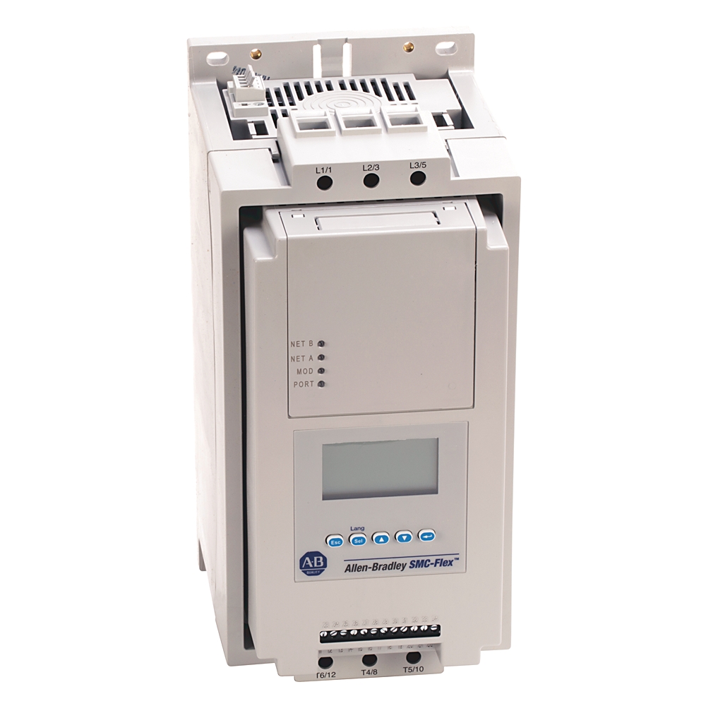
SMC Flex Smart Motor Controller
Serial #:
This product has not been verified. Please register your product to confirm authenticity.
Lifecycle status:
Active
Product at a glance
Replacement Available
Lifecycle status:
Active
Product at a glance
Replacement Available
Description
SMC-Flex, Solid State Controller, Open, 135 A, 25...100Hp @ 460V AC, Input Volt.: 200...480V, Control Volt.: 100...240V AC, Pump Control Option
Overview
Technical Specifications
General
Electrical
Environmental
Mechanical
Construction
Drawings
Documents
Certifications
Accessories
Alternative Products
Technotes
| Unique Product Identifier |
150-f135nbdb
|
|---|---|
| UPC |
662073047742
|
| Estimated Lead Time |
22 days
|
| Country of Origin |
Mexico
|
| Controller Rating |
135 A 25-100Hp @ 460V AC
|
|---|---|
| Control Voltage |
100...240V AC
|
| Sub Brand |
SMC Flex
|
| With display |
True
|
|---|---|
| Voltage type for actuating |
AC
|
| Rated operating voltage Ue |
200 V
|
| Rated control supply voltage at AC 50 Hz |
100 V
|
| Rated control supply voltage at AC 60 Hz |
100 V
|
| Overload current for line connected devices |
34 A
|
| Overload current for delta connected devices |
59 A
|
| Controller type |
Soft starter
|
| Control options |
Pump control
|
| Trip classes |
10, 15, 20 and 30
|
| Trip current rating |
117% of motor FLC
|
| Transformer control module |
75VA @ 100...240V AC (-15%, +10%)
|
| Heatsink fan rating |
20VA @ 110/120V AC or 220/240V AC
|
| DV/DT protection |
RC snubber network for power circuit
|
| Repetitive peak inverse voltage rating |
1400V per UL/CSA/NEMA for power circuit
|
| Operating frequency |
50/60 Hz for power circuit
|
| Line connected motor power, max |
90 kW @ 500V AC @ 50Hz, 3-phase
|
| Delta connected motor power, max |
75 kW @ 230V AC @ 50Hz, 3-phase
|
| Rated impulse voltage |
6000V per IEC for power circuit
|
| Dielectric withstand |
2500V per IEC for power circuit
|
| Line connected motor current |
34...135 A @ 600/Y/690V AC, 3-phase
|
| Delta connected motor current |
59...234A @ 500/575V AC, 3-phase
|
| Ampere tested european style, max |
6,9 gRB 73xxx400 6,6URD33xxx500 @ 690V for maximum FLC
|
| Ampere tested north american style, max |
A070URD33xxx500 @ 690V for maximum FLC
|
| Transient protection |
Metal oxide varistors: 220 J (optional) for power circuit
|
| Insulation voltage |
Rated 500V per IEC for power circuit
|
| Rated operational voltage |
200...480V AC (-15%, +10%) per UL/CSA/NEMA for power circuit
|
| Input OFF-state current |
<10 mA AC, <3 mA DC for control circuit @ input OFF-state voltage
|
| Short-circuit protection device list |
Standard fuse, circuit breaker and high capacity time delay class CC/J/L
|
| Number of contacts |
1 for auxiliary contacts
|
| High capacity available fault current, max |
70kA @ 600V, maximum current 400 A time delay Class J or Class L fuse for inside delta connected motors
|
| Type of current |
AC for auxiliary contacts
|
| Conventional thermal current (Ith) |
AC/DC: 5 A for auxiliary contacts
|
| Type of control circuit |
Electromagnetic relay for auxiliary contacts
|
| Type of contacts |
Progmable NO/NC for auxiliary contacts
|
| Utilization category |
MG 1 per UL/CSA/NEMA for power circuit
|
| Standard controller feature |
Status indication: stopped, starting, stopping, at speed, alarm and fault
|
| Standard available fault current, max |
70kA @ 690V for maximum FLC
|
| Optional controller feature |
SMB smart motor braking control: provides motor braking without additional equipment for applications that require the motor to stop quickly, braking current is adjustable from 0...400% of the motor’s full-load current rating
|
| Integrated motor overload protection |
True
|
| Short circuit protection device performance (SCPD) type |
Type 1
|
| Number of sensors, max |
6 for PTC input ratings
|
| Inrush current control module |
5A @ 24V DC (-15%, +10%)
|
| Voltage at PTC terminals (RPTC = open), max |
30V for PTC input ratings
|
| Transient watts control module |
60 W @ 24V DC (-15%, +10%)
|
| Steady state watts control module |
24 W @ 24V DC (-15%, +10%)
|
| Voltage at PTC terminals (RPTC = 4 kΩ), max |
<7.5 for PTC input ratings
|
| Response time |
800 ms for PTC input ratings
|
| Inrush time control module |
250 ms @ 24V DC (-15%, +10%)
|
| Transient time control module |
500 ms @ 24V DC (-15%, +10%)
|
| Cold resistance of PTC sensor chain, max |
1500 Ω for PTC input ratings
|
| Tachometer input |
0...5V DC @ 4.5V DC = 100% Speed
|
| Allen bradley power supply control module, min |
1606-XLP50E @ 24V DC (-15%, +10%)
|
| Short circuit trip resistance |
25 Ω ± 10 Ω for PTC input ratings
|
| Response resistance |
3400 Ω ± 150 Ω for PTC input ratings
|
| Reset resistance |
1600 Ω ± 100 Ω for PTC input ratings
|
| Input OFF-state voltage, max |
50V AC @ 10V DC/12V AC for control circuit
|
| Input ON-state voltage, min |
85V AC @ 19.2V DC/20.4V AC for control circuit
|
| Rated operational current |
3A @ 120V AC, 1.5A @ 240V AC for auxiliary contacts
|
| Input ON-state current |
20mA @ 120V AC/40mA @ 240V AC, 7.6mA @ 24V AC/DC for control circuit
|
| Contact type |
Auxiliary contacts 19/20 (Aux #1), 29/30 (Aux #2), 31/32 (Aux #3) and 33/34 (Aux #4)
|
| Steady state heat dissipation with control and fan power |
104 W
|
|---|---|
| Storage and transportation temperature |
-20 °C
|
| Humidity |
5...95% (noncondensing)
|
| Operating temperature |
Open: -5 to 50 °C (23 to 122 °F)
|
| Protection against electrical shock |
IP2X (with terminal covers) per IEC for power circuit
|
| EMC emission levels |
Radiated emission: Class A
|
| EMC immunity levels |
Surge transient: per EN/IEC 60947-4-2
|
| Altitude |
2000 m
|
| Pollution degree |
2
|
| Weight |
15 kg
|
|---|---|
| Shock |
Opsal: 5.5 G
|
| Width |
196.4 mm (7.74 in)
|
| Depth |
212.2 mm (8.35 in)
|
| Height |
443.7 mm (17.47 in)
|
| Power pole construction |
Heatsink hockey puck thyristor modular design
|
| Vibration |
Opsal: 1.0 G peak, 0.15 mm (0.006 in) displacement
|
| Make |
3600VA for auxiliary contacts
|
| Break |
360VA for auxiliary contacts
|
| Internal bypass |
True
|
| Function |
Single direction
|
| Power terminal markings |
NEMA, CENELEC EN50 012
|
| Control terminals |
ClAing yoke connection, M3 screw clA
|
| Line/load side power terminals |
One M10 x 1.5 diam hole per power pole
|
|---|---|
| Number of poles |
3
|
| Enclosure |
Open type
|
| Control modules construction |
Thermoset and thermoplastic moldings
|
| Metal parts construction |
Plated brass, copper or painted steel
|
| Drawings | |
|---|---|
| 2D Dimensions Drawing (PDF) | Download (PDF) |
| Product Drawing | Drawing (DWG) |
| Drawings |
|---|
| 2D Dimensions Drawing (PDF) Download (PDF) |
| Product Drawing Drawing (DWG) |
Sign in to your Rockwell Automation account to view and download technical drawings.
Sign In
| General | Publication |
|---|---|
| Product Cutsheet | -- |
| Specifications Sheet and Wiring Diagram | -- |
| Dimension Sheet | -- |
| Modes of Operation | -- |
| Circuit Protection Device And SCCR Tables | -- |
| Features | -- |
| Repair Parts List | -- |
| 3D Dimensions (STEP) | -- |
| Technical Data | Publication |
|---|---|
| 150-td009_-en-p | 150-TD009 |
| User Manual | Publication |
|---|---|
| 150-um008_-en-p | 150-UM008 |
Looking for more documentation?
Find curated technical documentation for this product in the Technical Documentation Center, or search our full Literature Library.
Visit the Technical Documentation Center
Search the Literature Library
- China CCC
- Eurasion Economic Community
- Australian RCM
- UKCA DOC
- MOROCCO DOC
This product was certified with the above certifications as of {}. Products sold before or after this date might carry different certifications. Please review the product label to check for the certifications your specific product carries.
Items Per Page:
Items Per Page:
| Technotes |
|---|
Looking for more Technotes?
Find questions and answers from Rockwell Automation technical experts for this product in our Knowledgebase.
Search Knowledgebase
Overview
| Unique Product Identifier |
150-f135nbdb
|
|---|---|
| UPC |
662073047742
|
| Estimated Lead Time |
22 days
|
| Country of Origin |
Mexico
|
Technical Specifications
| Controller Rating |
135 A 25-100Hp @ 460V AC
|
|---|---|
| Control Voltage |
100...240V AC
|
| Sub Brand |
SMC Flex
|
| With display |
True
|
|---|---|
| Voltage type for actuating |
AC
|
| Rated operating voltage Ue |
200 V
|
| Rated control supply voltage at AC 50 Hz |
100 V
|
| Rated control supply voltage at AC 60 Hz |
100 V
|
| Overload current for line connected devices |
34 A
|
| Overload current for delta connected devices |
59 A
|
| Controller type |
Soft starter
|
| Control options |
Pump control
|
| Trip classes |
10, 15, 20 and 30
|
| Trip current rating |
117% of motor FLC
|
| Transformer control module |
75VA @ 100...240V AC (-15%, +10%)
|
| Heatsink fan rating |
20VA @ 110/120V AC or 220/240V AC
|
| DV/DT protection |
RC snubber network for power circuit
|
| Repetitive peak inverse voltage rating |
1400V per UL/CSA/NEMA for power circuit
|
| Operating frequency |
50/60 Hz for power circuit
|
| Line connected motor power, max |
90 kW @ 500V AC @ 50Hz, 3-phase
|
| Delta connected motor power, max |
75 kW @ 230V AC @ 50Hz, 3-phase
|
| Rated impulse voltage |
6000V per IEC for power circuit
|
| Dielectric withstand |
2500V per IEC for power circuit
|
| Line connected motor current |
34...135 A @ 600/Y/690V AC, 3-phase
|
| Delta connected motor current |
59...234A @ 500/575V AC, 3-phase
|
| Ampere tested european style, max |
6,9 gRB 73xxx400 6,6URD33xxx500 @ 690V for maximum FLC
|
| Ampere tested north american style, max |
A070URD33xxx500 @ 690V for maximum FLC
|
| Transient protection |
Metal oxide varistors: 220 J (optional) for power circuit
|
| Insulation voltage |
Rated 500V per IEC for power circuit
|
| Rated operational voltage |
200...480V AC (-15%, +10%) per UL/CSA/NEMA for power circuit
|
| Input OFF-state current |
<10 mA AC, <3 mA DC for control circuit @ input OFF-state voltage
|
| Short-circuit protection device list |
Standard fuse, circuit breaker and high capacity time delay class CC/J/L
|
| Number of contacts |
1 for auxiliary contacts
|
| High capacity available fault current, max |
70kA @ 600V, maximum current 400 A time delay Class J or Class L fuse for inside delta connected motors
|
| Type of current |
AC for auxiliary contacts
|
| Conventional thermal current (Ith) |
AC/DC: 5 A for auxiliary contacts
|
| Type of control circuit |
Electromagnetic relay for auxiliary contacts
|
| Type of contacts |
Progmable NO/NC for auxiliary contacts
|
| Utilization category |
MG 1 per UL/CSA/NEMA for power circuit
|
| Standard controller feature |
Status indication: stopped, starting, stopping, at speed, alarm and fault
|
| Standard available fault current, max |
70kA @ 690V for maximum FLC
|
| Optional controller feature |
SMB smart motor braking control: provides motor braking without additional equipment for applications that require the motor to stop quickly, braking current is adjustable from 0...400% of the motor’s full-load current rating
|
| Integrated motor overload protection |
True
|
| Short circuit protection device performance (SCPD) type |
Type 1
|
| Number of sensors, max |
6 for PTC input ratings
|
| Inrush current control module |
5A @ 24V DC (-15%, +10%)
|
| Voltage at PTC terminals (RPTC = open), max |
30V for PTC input ratings
|
| Transient watts control module |
60 W @ 24V DC (-15%, +10%)
|
| Steady state watts control module |
24 W @ 24V DC (-15%, +10%)
|
| Voltage at PTC terminals (RPTC = 4 kΩ), max |
<7.5 for PTC input ratings
|
| Response time |
800 ms for PTC input ratings
|
| Inrush time control module |
250 ms @ 24V DC (-15%, +10%)
|
| Transient time control module |
500 ms @ 24V DC (-15%, +10%)
|
| Cold resistance of PTC sensor chain, max |
1500 Ω for PTC input ratings
|
| Tachometer input |
0...5V DC @ 4.5V DC = 100% Speed
|
| Allen bradley power supply control module, min |
1606-XLP50E @ 24V DC (-15%, +10%)
|
| Short circuit trip resistance |
25 Ω ± 10 Ω for PTC input ratings
|
| Response resistance |
3400 Ω ± 150 Ω for PTC input ratings
|
| Reset resistance |
1600 Ω ± 100 Ω for PTC input ratings
|
| Input OFF-state voltage, max |
50V AC @ 10V DC/12V AC for control circuit
|
| Input ON-state voltage, min |
85V AC @ 19.2V DC/20.4V AC for control circuit
|
| Rated operational current |
3A @ 120V AC, 1.5A @ 240V AC for auxiliary contacts
|
| Input ON-state current |
20mA @ 120V AC/40mA @ 240V AC, 7.6mA @ 24V AC/DC for control circuit
|
| Contact type |
Auxiliary contacts 19/20 (Aux #1), 29/30 (Aux #2), 31/32 (Aux #3) and 33/34 (Aux #4)
|
| Steady state heat dissipation with control and fan power |
104 W
|
|---|---|
| Storage and transportation temperature |
-20 °C
|
| Humidity |
5...95% (noncondensing)
|
| Operating temperature |
Open: -5 to 50 °C (23 to 122 °F)
|
| Protection against electrical shock |
IP2X (with terminal covers) per IEC for power circuit
|
| EMC emission levels |
Radiated emission: Class A
|
| EMC immunity levels |
Surge transient: per EN/IEC 60947-4-2
|
| Altitude |
2000 m
|
| Pollution degree |
2
|
| Weight |
15 kg
|
|---|---|
| Shock |
Opsal: 5.5 G
|
| Width |
196.4 mm (7.74 in)
|
| Depth |
212.2 mm (8.35 in)
|
| Height |
443.7 mm (17.47 in)
|
| Power pole construction |
Heatsink hockey puck thyristor modular design
|
| Vibration |
Opsal: 1.0 G peak, 0.15 mm (0.006 in) displacement
|
| Make |
3600VA for auxiliary contacts
|
| Break |
360VA for auxiliary contacts
|
| Internal bypass |
True
|
| Function |
Single direction
|
| Power terminal markings |
NEMA, CENELEC EN50 012
|
| Control terminals |
ClAing yoke connection, M3 screw clA
|
| Line/load side power terminals |
One M10 x 1.5 diam hole per power pole
|
|---|---|
| Number of poles |
3
|
| Enclosure |
Open type
|
| Control modules construction |
Thermoset and thermoplastic moldings
|
| Metal parts construction |
Plated brass, copper or painted steel
|
Drawings
| Drawings | |
|---|---|
| 2D Dimensions Drawing (PDF) | Download (PDF) |
| Product Drawing | Drawing (DWG) |
| Drawings |
|---|
| 2D Dimensions Drawing (PDF) Download (PDF) |
| Product Drawing Drawing (DWG) |
Sign in to your Rockwell Automation account to view and download technical drawings.
Sign In
Documents
|
Product Cutsheet
General
-- |
|
Specifications Sheet and Wiring Diagram
General
-- |
|
Dimension Sheet
General
-- |
|
Modes of Operation
General
-- |
|
Circuit Protection Device And SCCR Tables
General
-- |
|
Features
General
-- |
|
Repair Parts List
General
-- |
|
3D Dimensions (STEP)
General
-- |
|
150-td009_-en-p
Technical Data
150-TD009 |
|
150-um008_-en-p
User Manual
150-UM008 |
| General | Publication |
|---|---|
| Product Cutsheet | -- |
| Specifications Sheet and Wiring Diagram | -- |
| Dimension Sheet | -- |
| Modes of Operation | -- |
| Circuit Protection Device And SCCR Tables | -- |
| Features | -- |
| Repair Parts List | -- |
| 3D Dimensions (STEP) | -- |
| Technical Data | Publication |
| 150-td009_-en-p | 150-TD009 |
| User Manual | Publication |
| 150-um008_-en-p | 150-UM008 |
Looking for more documentation?
Find curated technical documentation for this product in the Technical Documentation Center, or search our full Literature Library.
Visit the Technical Documentation Center
Search the Literature Library
Certifications
- China CCC
- Eurasion Economic Community
- Australian RCM
- UKCA DOC
- MOROCCO DOC
This product was certified with the above certifications as of {}. Products sold before or after this date might carry different certifications. Please review the product label to check for the certifications your specific product carries.
Accessories
Items Per Page:
Alternative Products
Items Per Page:
Technotes
| Technotes |
|---|
Looking for more Technotes?
Find questions and answers from Rockwell Automation technical experts for this product in our Knowledgebase.
Search Knowledgebase
SMC Flex Smart Motor Controller
150-f135nbdb
Close
Print
Copyright ©2026 Rockwell Automation, Inc.