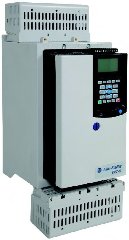
SMC-50 SOLID STATE MOTOR CONTROLLER 140A
SMC-50 SOLID STATE MOTOR CONTROLLER 140A
| Unique Product Identifier |
150-SB3NBR
|
|---|---|
| UPC |
612598994366
|
| Estimated Lead Time |
5 days
|
| Standard Warranty Duration |
1 year See details |
| Country of Origin |
Mexico
|
| Altitude |
2000 m (6560 ft) without derating, for ops above 2000...7000 m (6560...22965 ft) maximum, refer to Thermal Wizard
|
|---|---|
| Atmospheric protection |
ANSI/ISA - 71.04-2013, class G3 environment
|
| EMC emission levels |
Radiated emissions: Class A (per EN 60947-4-2)
|
| EMC immunity levels |
Surge transient per EN 60947-4-2
|
| Humidity |
5...95% (noncondensing)
|
| Mounting orientation |
Vertical
|
| Operating ambient temperature |
40 to 65 °C (104 to 149 °F) (refer to thermal wizard)
|
| Pollution degree |
2
|
| Protection against electrical shock |
IP2X (with optional terminal cover) per IEC
|
| Rated surrounding temperature range without derating |
-20 °C
|
| Storage and transportation temperature |
-25 °C
|
| Base power draw from control module with heat sink fan |
75 W @ 24V DC
|
|---|---|
| Continuous duty power structure heat dissipation |
420 W
|
| Control module battery type |
CR 2032 for control power
|
| Control power ride through |
22 ms for control power
|
| Controller rating |
140 A
|
| Controller type |
SMC-50
|
| DV/DT protection |
RC snubber network
|
| Delta connected motor current |
Normal/standard duty: 82...242A @ 400/415/460V AC, 3-phase
|
| Delta connected motor power |
Normal/standard duty: 75...200Hp @ 460V AC, 60 Hz, 3-phase
|
| Dielectric withstand |
2500V per IEC for power circuit
|
| High capacity available fault current, max |
65kA @ 600V, typical current 400 A time delay Class J or Class L fuse for inside delta connected motors
|
| Insulation voltage |
Rated 500V per IEC for power circuit
|
| Integrated motor overload protection |
True
|
| Line connected motor current |
Normal/standard duty: 47...140A @ 400/415/460V AC, 3-phase
|
| Line connected motor power |
Normal/standard duty: 40...100Hp @ 460V AC, 60 Hz, 3-phase
|
| Operating frequency |
47...63 Hz or DC for control power
|
| Option power adder |
4 W @ 24V DC, 20-COMM-X (for each option installed, add to base power to obtain total power requirement)
|
| Optional controller feature |
Param configuration/progming tools
|
| Output current, max |
300mA @ 24V DC supply (terminals 8 and 12) for control power
|
| Overload current for delta connected devices |
82 A
|
| Overload current for line connected devices |
47 A
|
| Overload type |
Electronic - using I2t algorithm
|
| Rated control supply voltage at DC |
24 V
|
| Rated impulse voltage |
6000V per IEC for power circuit
|
| Rated operating voltage Ue |
200 V
|
| Repetitive peak inverse voltage rating |
1400V per UL/CSA/NEMA for power circuit
|
| Short circuit protection device performance (SCPD) type |
Type 1
|
| Standard available fault current, max |
18kA @ 600V, typical current 700 A non-time delay fuse for inside delta connected motors
|
| Standard controller feature |
Torque control
|
| Transient protection |
Metal oxide varistors: 220 J
|
| Trip classes |
5...30
|
| Trip current rating |
118% of motor FLC
|
| Utilization category |
MG 1 per UL/CSA/NEMA for normal duty
|
| Voltage type for actuating |
DC
|
| With display |
False
|
| Control terminals |
ClAing yoke connection, M3 screw clA
|
|---|---|
| Degree of protection (IP) |
IP00
|
| Depth |
Line/wye: 304.8 mm
|
| Function |
Single direction
|
| Height |
Line/wye: 762 mm
|
| Power terminal lugs |
One 10.5 mm (0.41 in) diam hole per power pole
|
| Power terminal markings |
NEMA, CENELEC EN50 012
|
| Shock |
Opsal: 15 G
|
| Vibration |
Opsal: 1.0 G peak, 0.15 mm (0.006 in) displacement
|
| Width |
Line/wye: 609.6 mm
|
| Control modules |
Thermoset and thermoplastic moldings
|
|---|---|
| Enclosure |
Open type
|
| Horizontal clearance, min |
0 cm
|
| Metal parts |
Plated brass, copper or steel
|
| Number of poles |
3
|
| Power poles |
Heatsink hockey puck thyristor modular design
|
| Vertical clearance, min |
15 cm
|
| Drawings | |
|---|---|
| 3-Dimensional Drawing (STP) | Download (ZIP) |
| 2-Dimensional Drawings (DXF, DWG) | Download (ZIP) |
| Drawing File (PDF) | Download (PDF) |
| Drawings |
|---|
| 3-Dimensional Drawing (STP) Download (ZIP) |
| 2-Dimensional Drawings (DXF, DWG) Download (ZIP) |
| Drawing File (PDF) Download (PDF) |
| General | Publication |
|---|---|
| Web Link to Technical Data (Includes Specifications and Modes of Operation) | 150-TD009 |
| Product Cutsheet | -- |
| Circuit Protection Devices And SCCR Tables | -- |
| User Manual | Publication |
|---|---|
| 150-um011_-en-p | 150-UM011 |
- China CCC
- Eurasion Economic Community
- Australian RCM
- CE
- Korean KC
- American Bureau of Shippin
- UL Listed
This product was certified with the above certifications as of 2026-04-29. Products sold before or after this date might carry different certifications. Please review the product label to check for the certifications your specific product carries.
Looking for certification documents?
Explore certifications for this product and more in our comprehensive Literature Library.
| EU Importer Address |
Rockwell Automation N.V |
|---|---|
| EU Authorized Representative Address |
Rockwell Automation N.V |
| Technotes |
|---|
Overview
| Unique Product Identifier |
150-SB3NBR
|
|---|---|
| UPC |
612598994366
|
| Estimated Lead Time |
5 days
|
| Standard Warranty Duration |
1 year See details |
| Country of Origin |
Mexico
|
Compliance & Environment
| Altitude |
2000 m (6560 ft) without derating, for ops above 2000...7000 m (6560...22965 ft) maximum, refer to Thermal Wizard
|
|---|---|
| Atmospheric protection |
ANSI/ISA - 71.04-2013, class G3 environment
|
| EMC emission levels |
Radiated emissions: Class A (per EN 60947-4-2)
|
| EMC immunity levels |
Surge transient per EN 60947-4-2
|
| Humidity |
5...95% (noncondensing)
|
| Mounting orientation |
Vertical
|
| Operating ambient temperature |
40 to 65 °C (104 to 149 °F) (refer to thermal wizard)
|
| Pollution degree |
2
|
| Protection against electrical shock |
IP2X (with optional terminal cover) per IEC
|
| Rated surrounding temperature range without derating |
-20 °C
|
| Storage and transportation temperature |
-25 °C
|
Electrical & Connectivity
| Base power draw from control module with heat sink fan |
75 W @ 24V DC
|
|---|---|
| Continuous duty power structure heat dissipation |
420 W
|
| Control module battery type |
CR 2032 for control power
|
| Control power ride through |
22 ms for control power
|
| Controller rating |
140 A
|
| Controller type |
SMC-50
|
| DV/DT protection |
RC snubber network
|
| Delta connected motor current |
Normal/standard duty: 82...242A @ 400/415/460V AC, 3-phase
|
| Delta connected motor power |
Normal/standard duty: 75...200Hp @ 460V AC, 60 Hz, 3-phase
|
| Dielectric withstand |
2500V per IEC for power circuit
|
| High capacity available fault current, max |
65kA @ 600V, typical current 400 A time delay Class J or Class L fuse for inside delta connected motors
|
| Insulation voltage |
Rated 500V per IEC for power circuit
|
| Integrated motor overload protection |
True
|
| Line connected motor current |
Normal/standard duty: 47...140A @ 400/415/460V AC, 3-phase
|
| Line connected motor power |
Normal/standard duty: 40...100Hp @ 460V AC, 60 Hz, 3-phase
|
| Operating frequency |
47...63 Hz or DC for control power
|
| Option power adder |
4 W @ 24V DC, 20-COMM-X (for each option installed, add to base power to obtain total power requirement)
|
| Optional controller feature |
Param configuration/progming tools
|
| Output current, max |
300mA @ 24V DC supply (terminals 8 and 12) for control power
|
| Overload current for delta connected devices |
82 A
|
| Overload current for line connected devices |
47 A
|
| Overload type |
Electronic - using I2t algorithm
|
| Rated control supply voltage at DC |
24 V
|
| Rated impulse voltage |
6000V per IEC for power circuit
|
| Rated operating voltage Ue |
200 V
|
| Repetitive peak inverse voltage rating |
1400V per UL/CSA/NEMA for power circuit
|
| Short circuit protection device performance (SCPD) type |
Type 1
|
| Standard available fault current, max |
18kA @ 600V, typical current 700 A non-time delay fuse for inside delta connected motors
|
| Standard controller feature |
Torque control
|
| Transient protection |
Metal oxide varistors: 220 J
|
| Trip classes |
5...30
|
| Trip current rating |
118% of motor FLC
|
| Utilization category |
MG 1 per UL/CSA/NEMA for normal duty
|
| Voltage type for actuating |
DC
|
| With display |
False
|
Physical Characteristics
| Control terminals |
ClAing yoke connection, M3 screw clA
|
|---|---|
| Degree of protection (IP) |
IP00
|
| Depth |
Line/wye: 304.8 mm
|
| Function |
Single direction
|
| Height |
Line/wye: 762 mm
|
| Power terminal lugs |
One 10.5 mm (0.41 in) diam hole per power pole
|
| Power terminal markings |
NEMA, CENELEC EN50 012
|
| Shock |
Opsal: 15 G
|
| Vibration |
Opsal: 1.0 G peak, 0.15 mm (0.006 in) displacement
|
| Width |
Line/wye: 609.6 mm
|
| Control modules |
Thermoset and thermoplastic moldings
|
|---|---|
| Enclosure |
Open type
|
| Horizontal clearance, min |
0 cm
|
| Metal parts |
Plated brass, copper or steel
|
| Number of poles |
3
|
| Power poles |
Heatsink hockey puck thyristor modular design
|
| Vertical clearance, min |
15 cm
|
Drawings
| Drawings | |
|---|---|
| 3-Dimensional Drawing (STP) | Download (ZIP) |
| 2-Dimensional Drawings (DXF, DWG) | Download (ZIP) |
| Drawing File (PDF) | Download (PDF) |
| Drawings |
|---|
| 3-Dimensional Drawing (STP) Download (ZIP) |
| 2-Dimensional Drawings (DXF, DWG) Download (ZIP) |
| Drawing File (PDF) Download (PDF) |
Documents
|
Web Link to Technical Data (Includes Specifications and Modes of Operation)
General
150-TD009 |
|
Product Cutsheet
General
-- |
|
Circuit Protection Devices And SCCR Tables
General
-- |
|
150-um011_-en-p
User Manual
150-UM011 |
| General | Publication |
|---|---|
| Web Link to Technical Data (Includes Specifications and Modes of Operation) | 150-TD009 |
| Product Cutsheet | -- |
| Circuit Protection Devices And SCCR Tables | -- |
| User Manual | Publication |
| 150-um011_-en-p | 150-UM011 |
Certifications
- China CCC
- Eurasion Economic Community
- Australian RCM
- CE
- Korean KC
- American Bureau of Shippin
- UL Listed
This product was certified with the above certifications as of 2026-04-29. Products sold before or after this date might carry different certifications. Please review the product label to check for the certifications your specific product carries.
Looking for certification documents?
Explore certifications for this product and more in our comprehensive Literature Library.
| EU Importer Address |
Rockwell Automation N.V |
|---|---|
| EU Authorized Representative Address |
Rockwell Automation N.V |
Accessories
Alternative Products
Technotes
| Technotes |
|---|