View all SMC-3 Smart Motor Controller
Preferred
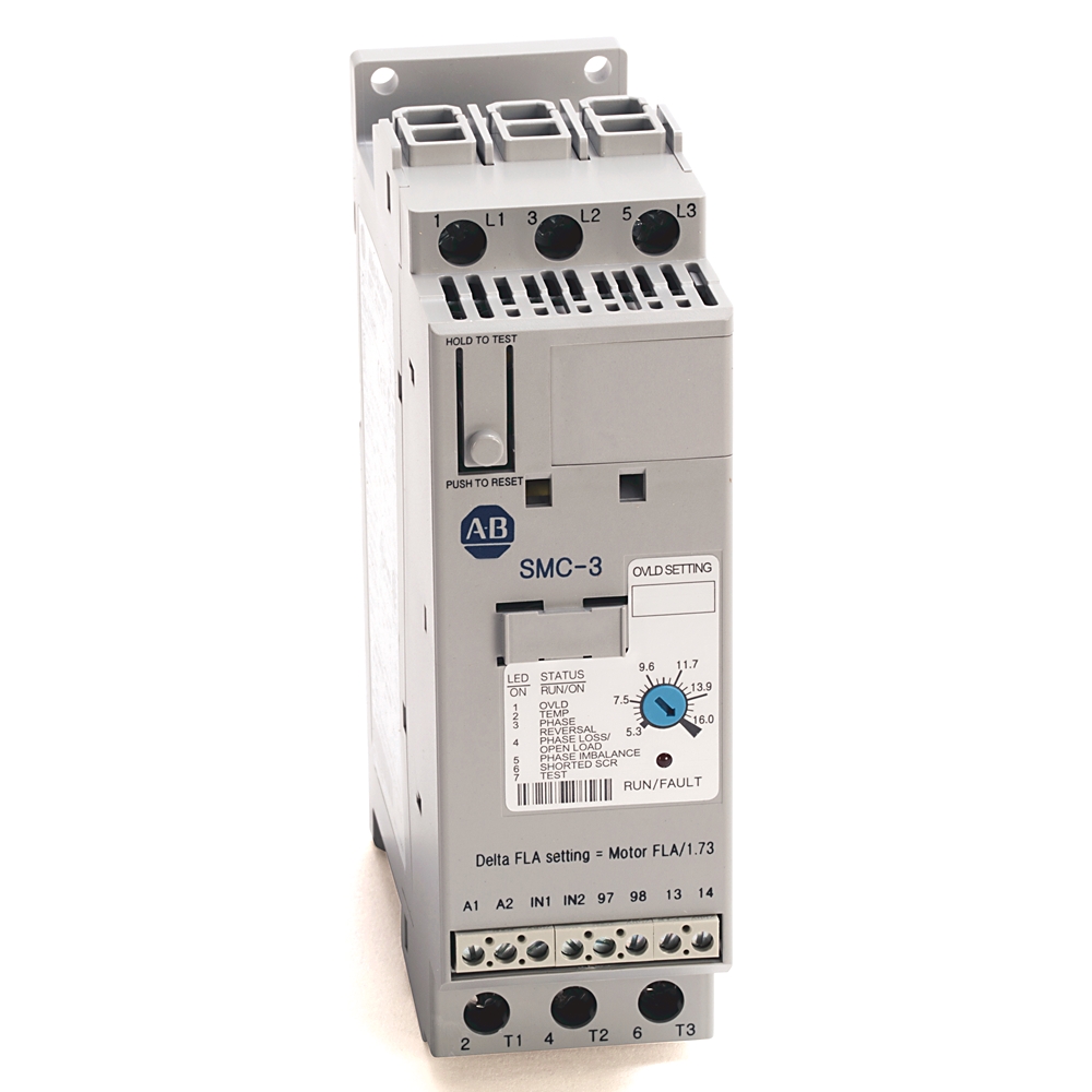
150-c25nbd
SMC-3 25A Smart Motor Controller
Serial #:
This product has not been verified. Please register your product to confirm authenticity.
Lifecycle status:
Active
Lifecycle status:
Active
Technical Specifications
General
Electrical
Mechanical
Environmental
Construction
Drawings
Documents
Certifications
Accessories
Alternative Products
Technotes
| Sub Brand |
SMC-3
|
|---|
| With display |
False
|
|---|---|
| Voltage type for actuating |
AC/DC
|
| Rated operating voltage Ue |
200 V
|
| Rated control supply voltage at AC 50 Hz |
100 V
|
| Rated control supply voltage at AC 60 Hz |
100 V
|
| Overload current |
8.3 A
|
| Controller type |
SMC-3
|
| DV/DT protection |
1000V/µs for power circuit
|
| Repetitive peak voltage |
1400V per UL/CSA/NEMA for power circuit
|
| Operating frequency |
50/60 Hz per UL/CSA/NEMA for power circuit
|
| Line connected motor power, max |
7.5...15Hp @ 460V AC, 60 Hz, 3-phase
|
| Delta connected motor power, max |
7.5...20Hp @ 460V AC, 60 Hz, 3-phase
|
| Overvoltage category |
III per IEC for side mount auxiliary contacts
|
| Rated impulse voltage |
6 kV for power circuit
|
| Dielectric withstand |
2500V AC per IEC for power circuit
|
| Line connected motor current |
9.2...25A @ 380/400/415/460V AC, 3-phase
|
| Delta connected motor current |
14.3...43A @ 380/400/415/460V AC, 3-phase
|
| Insulation voltage |
Rated 600V AC per UL/CSA/NEMA for power circuit
|
| Rated operational voltage |
250V AC/30V DC per UL/CSA/NEMA for Side mount auxiliary contacts
|
| Rated control power during start with fan |
215mA @ 120V AC/180mA @ 240V AC, 800mA @ 24V DC/660mA @ 24V AC
|
| Input OFF-state current |
<10 mA, <12 mA @ input OFF-state voltage (IN1, IN2) for control circuit
|
| Short-circuit protection device list |
Non-time delay Thermal magnetic circuit breaker High capacity time delay class CC/J/L
|
| Number of contacts |
TB-97, -98 (OVLD/Fault): 1 for auxiliary contacts
|
| High capacity available fault current, max |
70kA @ 600V, maximum current 90 A time delay Class J or Class L fuse for inside delta connected motors
|
| Type of current |
TB-97, -98 (OVLD/Fault): AC/DC for auxiliary contacts
|
| Conventional thermal current (Ith) |
TB-97, -98 (OVLD/Fault): 1 A for auxiliary contacts
|
| Type of control circuit |
TB-97, -98 (OVLD/Fault): Electromagnetic relay for auxiliary contacts
|
| Type of contacts |
TB-97, -98 (OVLD/Fault): Normally Open (N.O.) for auxiliary contacts
|
| Utilization category |
TB-23, -24 (normal/up-to-speed), TB-33, -34 (normal/up-to-speed): C300/R150 per UL/CSA/NEMA for Side mount auxiliary contacts
|
| Rated operational current, max |
TB-97, -98 (OVLD/Fault): 0.6A @ 120V AC and 0.3A @ 240V AC for auxiliary contacts
|
| Standard controller feature |
Soft stop
|
| Standard available fault current, max |
5 kA @ maximum standard fuse 150 A for delta device opsal current rating
|
| Integrated motor overload protection |
True
|
| Short circuit protection device performance (SCPD) type |
Type 1
|
| Selectable overload trip class |
Trip Class 10, 15, or 20
|
| Selectable start times |
2, 5, 10, 15, 20, 25, or 30 s
|
| Input OFF-state voltage (IN1, IN2), max |
40V AC @ 17V DC/12V AC for control circuit
|
| Selectable current limit |
150%, 250%, 350%, and 450% of full load current
|
| Input ON-state voltage, during start (IN1, IN2) |
85V AC @ 19.2V DC/19.2V AC minimum for control circuit
|
| Rated control power during start without fan |
205mA @ 120V AC/145mA @ 240V AC, 705mA @ 24V DC/580mA @ 24V AC
|
| Input ON-state current (IN1, IN2) |
9.8mA @ 120V AC/19.6mA @ 240V AC for control circuit, 7.3mA @ 24V AC/DC for control circuit
|
| Degree of protection (IP) |
IP2X
|
|---|---|
| Weight |
0.86 kg
|
| Shock |
Opsal: 15 G
|
| Width |
44.8 mm (1.76 in)
|
| Depth |
110 mm (4.33 in)
|
| Height |
139.7 mm (5.5 in)
|
| Cable size |
2.5...25 mm² (14...4 AWG) for line power terminals
|
| Vibration |
Opsal: 1.0 G peak, 0.15 mm (0.006 in) displacement
|
| Make |
TB-97, -98 (OVLD/Fault): 432VA for auxiliary contacts
|
| Break |
TB-97, -98 (OVLD/Fault): 72VA for auxiliary contacts
|
| Tightening torque |
2.3...3.4 Nm (30 in-lb) for line power terminals, 4.0 Nm (35 in-lb) if 25 mm² (4 AWG) wire in top terminal for line power terminal
|
| Internal bypass |
True
|
| Function |
Single direction
|
| Selectable kick start - 450% FLA |
0, 0.5, 1.0, or 1.5 s
|
| Selectable initial torque |
15%, 25%, 35%, and 65% of locked rotor torque
|
| Selectable soft stop |
Off, 100%, 200%, or 300% of the start time setting when wired
|
| Steady state heat dissipation |
17 W
|
|---|---|
| Storage and transportation temperature |
-25 °C
|
| Rated surrounding temperature range without derating |
-5 °C
|
| Humidity |
5...95% noncondensing
|
| Operating temperature |
Open: -5 to 50 °C (23 to 122 °F)
|
| EMC emission levels |
Radiated emission: Class A per IEC
|
| EMC immunity levels |
Surge transient: per EN/IEC 60947-4-2 per IEC
|
| Altitude |
2000 m
|
| Pollution degree |
2
|
| Mounting hole size |
4.6 mm
|
|---|---|
| Number of poles |
Equipment is designed for 3-phase only for power circuit
|
| Enclosure |
Open type
|
| Drawings | |
|---|---|
| 3-Dimensional STEP model (STP) | Download (ZIP) |
| Product Drawing | Drawing (DWG) |
| Drawings |
|---|
| 3-Dimensional STEP model (STP) Download (ZIP) |
| Product Drawing Drawing (DWG) |
Sign in to your Rockwell Automation account to view and download technical drawings.
Sign In
| General | Publication |
|---|---|
| Wiring | -- |
| Features and Modes of Operation | -- |
| Dimension Sheet (Catalog) | -- |
| Specifications Sheet | -- |
| Product Cutsheet | -- |
| OL Trip Curves and Starts per Hour Curves | -- |
| Dimension Sheet (PDF) | -- |
| Circuit Protection Device And SCCR Tables | -- |
| Installation Instructions | Publication |
|---|---|
| 150-in044_-en-e | 150-IN044 |
| Technical Data | Publication |
|---|---|
| 150-td009_-en-p | 150-TD009 |
Looking for more documentation?
Find curated technical documentation for this product in the Technical Documentation Center, or search our full Literature Library.
Visit the Technical Documentation Center
Search the Literature Library
- Eurasion Economic Community
- Australian RCM
- China CCC
- MOROCCO DOC
- UKCA DOC
This product was certified with the above certifications as of {}. Products sold before or after this date might carry different certifications. Please review the product label to check for the certifications your specific product carries.
Items Per Page:
Items Per Page:
| Technotes |
|---|
Looking for more Technotes?
Find questions and answers from Rockwell Automation technical experts for this product in our Knowledgebase.
Search Knowledgebase
Technical Specifications
| Sub Brand |
SMC-3
|
|---|
| With display |
False
|
|---|---|
| Voltage type for actuating |
AC/DC
|
| Rated operating voltage Ue |
200 V
|
| Rated control supply voltage at AC 50 Hz |
100 V
|
| Rated control supply voltage at AC 60 Hz |
100 V
|
| Overload current |
8.3 A
|
| Controller type |
SMC-3
|
| DV/DT protection |
1000V/µs for power circuit
|
| Repetitive peak voltage |
1400V per UL/CSA/NEMA for power circuit
|
| Operating frequency |
50/60 Hz per UL/CSA/NEMA for power circuit
|
| Line connected motor power, max |
7.5...15Hp @ 460V AC, 60 Hz, 3-phase
|
| Delta connected motor power, max |
7.5...20Hp @ 460V AC, 60 Hz, 3-phase
|
| Overvoltage category |
III per IEC for side mount auxiliary contacts
|
| Rated impulse voltage |
6 kV for power circuit
|
| Dielectric withstand |
2500V AC per IEC for power circuit
|
| Line connected motor current |
9.2...25A @ 380/400/415/460V AC, 3-phase
|
| Delta connected motor current |
14.3...43A @ 380/400/415/460V AC, 3-phase
|
| Insulation voltage |
Rated 600V AC per UL/CSA/NEMA for power circuit
|
| Rated operational voltage |
250V AC/30V DC per UL/CSA/NEMA for Side mount auxiliary contacts
|
| Rated control power during start with fan |
215mA @ 120V AC/180mA @ 240V AC, 800mA @ 24V DC/660mA @ 24V AC
|
| Input OFF-state current |
<10 mA, <12 mA @ input OFF-state voltage (IN1, IN2) for control circuit
|
| Short-circuit protection device list |
Non-time delay Thermal magnetic circuit breaker High capacity time delay class CC/J/L
|
| Number of contacts |
TB-97, -98 (OVLD/Fault): 1 for auxiliary contacts
|
| High capacity available fault current, max |
70kA @ 600V, maximum current 90 A time delay Class J or Class L fuse for inside delta connected motors
|
| Type of current |
TB-97, -98 (OVLD/Fault): AC/DC for auxiliary contacts
|
| Conventional thermal current (Ith) |
TB-97, -98 (OVLD/Fault): 1 A for auxiliary contacts
|
| Type of control circuit |
TB-97, -98 (OVLD/Fault): Electromagnetic relay for auxiliary contacts
|
| Type of contacts |
TB-97, -98 (OVLD/Fault): Normally Open (N.O.) for auxiliary contacts
|
| Utilization category |
TB-23, -24 (normal/up-to-speed), TB-33, -34 (normal/up-to-speed): C300/R150 per UL/CSA/NEMA for Side mount auxiliary contacts
|
| Rated operational current, max |
TB-97, -98 (OVLD/Fault): 0.6A @ 120V AC and 0.3A @ 240V AC for auxiliary contacts
|
| Standard controller feature |
Soft stop
|
| Standard available fault current, max |
5 kA @ maximum standard fuse 150 A for delta device opsal current rating
|
| Integrated motor overload protection |
True
|
| Short circuit protection device performance (SCPD) type |
Type 1
|
| Selectable overload trip class |
Trip Class 10, 15, or 20
|
| Selectable start times |
2, 5, 10, 15, 20, 25, or 30 s
|
| Input OFF-state voltage (IN1, IN2), max |
40V AC @ 17V DC/12V AC for control circuit
|
| Selectable current limit |
150%, 250%, 350%, and 450% of full load current
|
| Input ON-state voltage, during start (IN1, IN2) |
85V AC @ 19.2V DC/19.2V AC minimum for control circuit
|
| Rated control power during start without fan |
205mA @ 120V AC/145mA @ 240V AC, 705mA @ 24V DC/580mA @ 24V AC
|
| Input ON-state current (IN1, IN2) |
9.8mA @ 120V AC/19.6mA @ 240V AC for control circuit, 7.3mA @ 24V AC/DC for control circuit
|
| Degree of protection (IP) |
IP2X
|
|---|---|
| Weight |
0.86 kg
|
| Shock |
Opsal: 15 G
|
| Width |
44.8 mm (1.76 in)
|
| Depth |
110 mm (4.33 in)
|
| Height |
139.7 mm (5.5 in)
|
| Cable size |
2.5...25 mm² (14...4 AWG) for line power terminals
|
| Vibration |
Opsal: 1.0 G peak, 0.15 mm (0.006 in) displacement
|
| Make |
TB-97, -98 (OVLD/Fault): 432VA for auxiliary contacts
|
| Break |
TB-97, -98 (OVLD/Fault): 72VA for auxiliary contacts
|
| Tightening torque |
2.3...3.4 Nm (30 in-lb) for line power terminals, 4.0 Nm (35 in-lb) if 25 mm² (4 AWG) wire in top terminal for line power terminal
|
| Internal bypass |
True
|
| Function |
Single direction
|
| Selectable kick start - 450% FLA |
0, 0.5, 1.0, or 1.5 s
|
| Selectable initial torque |
15%, 25%, 35%, and 65% of locked rotor torque
|
| Selectable soft stop |
Off, 100%, 200%, or 300% of the start time setting when wired
|
| Steady state heat dissipation |
17 W
|
|---|---|
| Storage and transportation temperature |
-25 °C
|
| Rated surrounding temperature range without derating |
-5 °C
|
| Humidity |
5...95% noncondensing
|
| Operating temperature |
Open: -5 to 50 °C (23 to 122 °F)
|
| EMC emission levels |
Radiated emission: Class A per IEC
|
| EMC immunity levels |
Surge transient: per EN/IEC 60947-4-2 per IEC
|
| Altitude |
2000 m
|
| Pollution degree |
2
|
| Mounting hole size |
4.6 mm
|
|---|---|
| Number of poles |
Equipment is designed for 3-phase only for power circuit
|
| Enclosure |
Open type
|
Drawings
| Drawings | |
|---|---|
| 3-Dimensional STEP model (STP) | Download (ZIP) |
| Product Drawing | Drawing (DWG) |
| Drawings |
|---|
| 3-Dimensional STEP model (STP) Download (ZIP) |
| Product Drawing Drawing (DWG) |
Sign in to your Rockwell Automation account to view and download technical drawings.
Sign In
Documents
|
Wiring
General
-- |
|
Features and Modes of Operation
General
-- |
|
Dimension Sheet (Catalog)
General
-- |
|
Specifications Sheet
General
-- |
|
Product Cutsheet
General
-- |
|
OL Trip Curves and Starts per Hour Curves
General
-- |
|
Dimension Sheet (PDF)
General
-- |
|
Circuit Protection Device And SCCR Tables
General
-- |
|
150-in044_-en-e
Installation Instructions
150-IN044 |
|
150-td009_-en-p
Technical Data
150-TD009 |
| General | Publication |
|---|---|
| Wiring | -- |
| Features and Modes of Operation | -- |
| Dimension Sheet (Catalog) | -- |
| Specifications Sheet | -- |
| Product Cutsheet | -- |
| OL Trip Curves and Starts per Hour Curves | -- |
| Dimension Sheet (PDF) | -- |
| Circuit Protection Device And SCCR Tables | -- |
| Installation Instructions | Publication |
| 150-in044_-en-e | 150-IN044 |
| Technical Data | Publication |
| 150-td009_-en-p | 150-TD009 |
Looking for more documentation?
Find curated technical documentation for this product in the Technical Documentation Center, or search our full Literature Library.
Visit the Technical Documentation Center
Search the Literature Library
Certifications
- Eurasion Economic Community
- Australian RCM
- China CCC
- MOROCCO DOC
- UKCA DOC
This product was certified with the above certifications as of {}. Products sold before or after this date might carry different certifications. Please review the product label to check for the certifications your specific product carries.
Accessories
Items Per Page:
Alternative Products
Items Per Page:
Technotes
| Technotes |
|---|
Looking for more Technotes?
Find questions and answers from Rockwell Automation technical experts for this product in our Knowledgebase.
Search Knowledgebase
SMC-3 25A Smart Motor Controller
150-c25nbd
Close
Print
Copyright ©2026 Rockwell Automation, Inc.