1494U-J200-C5-HJ-LC-M-PC
Disconnect Kits
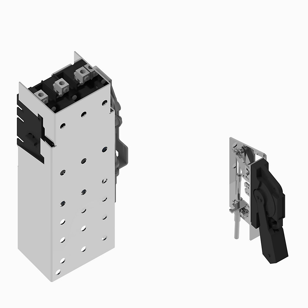
Product at a glance
Product at a glance
| Connection type |
Switch body : glass-filled thermoplastic
|
|---|---|
| Efficiency |
-20
|
| Flicker |
10A @ 250V AC, 0.3A @ 250V DC per NEMA/EEMAC
|
| Fuse block option |
110 kW @ 500...600V AC, 3-phase, 50 Hz
|
| Hold-up time |
-40
|
| Individual harmonics (DC-127th) |
40Hp @ 600V DC per UL and CSA
|
| Interharmonics |
AC 15, DC 13 to IEC/EN60947-5-1 and UL 508, 17V @ 5mA min per IEC
|
| LED status |
8000
|
| Level-5 lens color |
2000 m per IEC 947-1
|
| NEMA rating designation |
200A @ 250/600V DC
|
| Operating distance |
2200V @ 1min
|
| Operational range |
200000A @ 600V AC : with class J or class R fuses
|
| Power losses |
16
|
| Rated input current |
Lug to terminal : 175 in-lb
|
| Rated output current |
600V @ 200A switch, 200 A type J fuse clips
|
| Special family function |
5
|
| Special product function |
Knife switch style handle
|
| Spot size |
90% @ 20°C (68 °F) and 50% @ 40°C (104 °F) per IEC 947-1
|
| Sub group |
-20
|
| Temperature, max |
Protective cover
|
| Transient detect |
AC 15, DC 13 to IEC/EN60947-5-1 and UL 508, 5V @ 1mA min per IEC
|
| Number of poles |
3
|
|---|---|
| Rated permanent current Iu |
200 A
|
| Max. rated operation voltage Ue AC |
600 V
|
| Type of control element |
Long turning handle
|
| Switching frequency, max |
5 ops/m
|
| Continuous current rating |
200 A
|
| Number of switches |
1
|
| Motor drive optional |
False
|
| Voltage release optional |
False
|
| Type of electrical connection of main circuit |
Screw connection
|
| Switch and fuse rating (fusing) |
600V @ 200A switch, 200 A Type J fuse clips
|
| Short circuit withstand capability |
200000A @ 600V AC, with class J or class R fuses
|
| KW rating, max |
90 kW @ 380...440V AC, 3-phase, 50 Hz per IEC (AC23)
|
| Hp rating, max |
60Hp @ 230V AC, 3-phase, 60 Hz per UL and CSA
|
| Auxiliary contact electrical ratings |
AC 15, DC 13 to IEC/EN60947-5-1 and UL 508, 17V @ 5mA minimum per IEC
|
| Electrical interlock ratings |
Standard contact 2 NO: 10A @ 250V AC, 0.3A @ 250V DC per NEMA/EEMAC
|
| With pre-assembled cabling |
False
|
| Dielectric strength |
2200V @ 1min
|
| Operating handle style |
Knife switch style handle
|
| Interlockable |
True
|
|---|---|
| Recommended torque |
Switch side: 275 in-lb
|
| Version as main switch |
True
|
| Factory option |
Protective cover
|
| Mechanical life operations |
8000
|
| Degree of protection |
Operating handles: painted Type 1, 3R, 4, 12
|
| Material |
Switches, mechanisms and accessory kits: Zinc-plated Steel, RoHS compliant finish
|
| Width |
8.41 in
|
|---|---|
| Device construction |
Built-in device fixed built-in technique
|
| Height |
12.4 in
|
| Depth |
4.71 in
|
| Conductor size |
Single Port copper lug: 6…250 AWG @ copper conductor
|
| Altitude |
2000 m (6562 ft) per IEC 947-1
|
|---|---|
| Ambient temperature |
Storage: -40...65 °C (-40...149 °F)
|
| Relative humidity |
90% @ 20°C (68 °F) and 50% @ 40°C (104 °F) per IEC 947-1
|
| Drawings | |
|---|---|
| 3-Dimensional STEP model (STP) | Download (ZIP) |
| 2-Dimensional Drawing (PDF) | Download (PDF) |
| Product Drawing | Drawing (DXF) |
| Drawings |
|---|
| 3-Dimensional STEP model (STP) Download (ZIP) |
| 2-Dimensional Drawing (PDF) Download (PDF) |
| Product Drawing Drawing (DXF) |
Sign in to your Rockwell Automation account to view and download technical drawings.
Sign In
| General | Publication |
|---|---|
| Product Cutsheet | -- |
| Technical Data | Publication |
|---|---|
| 1494-td002_-en-p | 1494-TD002 |
Looking for more documentation?
Find curated technical documentation for this product in the Technical Documentation Center, or search our full Literature Library.
Search the Literature Library
- CE
- China CCC
This product was certified with the above certifications as of {}. Products sold before or after this date might carry different certifications. Please review the product label to check for the certifications your specific product carries.
Looking for more Technotes?
Find questions and answers from Rockwell Automation technical experts for this product in our Knowledgebase.
Search Knowledgebase
Technical Specifications
| Connection type |
Switch body : glass-filled thermoplastic
|
|---|---|
| Efficiency |
-20
|
| Flicker |
10A @ 250V AC, 0.3A @ 250V DC per NEMA/EEMAC
|
| Fuse block option |
110 kW @ 500...600V AC, 3-phase, 50 Hz
|
| Hold-up time |
-40
|
| Individual harmonics (DC-127th) |
40Hp @ 600V DC per UL and CSA
|
| Interharmonics |
AC 15, DC 13 to IEC/EN60947-5-1 and UL 508, 17V @ 5mA min per IEC
|
| LED status |
8000
|
| Level-5 lens color |
2000 m per IEC 947-1
|
| NEMA rating designation |
200A @ 250/600V DC
|
| Operating distance |
2200V @ 1min
|
| Operational range |
200000A @ 600V AC : with class J or class R fuses
|
| Power losses |
16
|
| Rated input current |
Lug to terminal : 175 in-lb
|
| Rated output current |
600V @ 200A switch, 200 A type J fuse clips
|
| Special family function |
5
|
| Special product function |
Knife switch style handle
|
| Spot size |
90% @ 20°C (68 °F) and 50% @ 40°C (104 °F) per IEC 947-1
|
| Sub group |
-20
|
| Temperature, max |
Protective cover
|
| Transient detect |
AC 15, DC 13 to IEC/EN60947-5-1 and UL 508, 5V @ 1mA min per IEC
|
| Number of poles |
3
|
|---|---|
| Rated permanent current Iu |
200 A
|
| Max. rated operation voltage Ue AC |
600 V
|
| Type of control element |
Long turning handle
|
| Switching frequency, max |
5 ops/m
|
| Continuous current rating |
200 A
|
| Number of switches |
1
|
| Motor drive optional |
False
|
| Voltage release optional |
False
|
| Type of electrical connection of main circuit |
Screw connection
|
| Switch and fuse rating (fusing) |
600V @ 200A switch, 200 A Type J fuse clips
|
| Short circuit withstand capability |
200000A @ 600V AC, with class J or class R fuses
|
| KW rating, max |
90 kW @ 380...440V AC, 3-phase, 50 Hz per IEC (AC23)
|
| Hp rating, max |
60Hp @ 230V AC, 3-phase, 60 Hz per UL and CSA
|
| Auxiliary contact electrical ratings |
AC 15, DC 13 to IEC/EN60947-5-1 and UL 508, 17V @ 5mA minimum per IEC
|
| Electrical interlock ratings |
Standard contact 2 NO: 10A @ 250V AC, 0.3A @ 250V DC per NEMA/EEMAC
|
| With pre-assembled cabling |
False
|
| Dielectric strength |
2200V @ 1min
|
| Operating handle style |
Knife switch style handle
|
| Interlockable |
True
|
|---|---|
| Recommended torque |
Switch side: 275 in-lb
|
| Version as main switch |
True
|
| Factory option |
Protective cover
|
| Mechanical life operations |
8000
|
| Degree of protection |
Operating handles: painted Type 1, 3R, 4, 12
|
| Material |
Switches, mechanisms and accessory kits: Zinc-plated Steel, RoHS compliant finish
|
| Width |
8.41 in
|
|---|---|
| Device construction |
Built-in device fixed built-in technique
|
| Height |
12.4 in
|
| Depth |
4.71 in
|
| Conductor size |
Single Port copper lug: 6…250 AWG @ copper conductor
|
| Altitude |
2000 m (6562 ft) per IEC 947-1
|
|---|---|
| Ambient temperature |
Storage: -40...65 °C (-40...149 °F)
|
| Relative humidity |
90% @ 20°C (68 °F) and 50% @ 40°C (104 °F) per IEC 947-1
|
Drawings
| Drawings | |
|---|---|
| 3-Dimensional STEP model (STP) | Download (ZIP) |
| 2-Dimensional Drawing (PDF) | Download (PDF) |
| Product Drawing | Drawing (DXF) |
| Drawings |
|---|
| 3-Dimensional STEP model (STP) Download (ZIP) |
| 2-Dimensional Drawing (PDF) Download (PDF) |
| Product Drawing Drawing (DXF) |
Sign in to your Rockwell Automation account to view and download technical drawings.
Sign In
Documents
|
Product Cutsheet
General
-- |
|
1494-td002_-en-p
Technical Data
1494-TD002 |
| General | Publication |
|---|---|
| Product Cutsheet | -- |
| Technical Data | Publication |
| 1494-td002_-en-p | 1494-TD002 |
Looking for more documentation?
Find curated technical documentation for this product in the Technical Documentation Center, or search our full Literature Library.
Search the Literature Library
Certifications
- CE
- China CCC
This product was certified with the above certifications as of {}. Products sold before or after this date might carry different certifications. Please review the product label to check for the certifications your specific product carries.
Alternative Products
Technotes
Looking for more Technotes?
Find questions and answers from Rockwell Automation technical experts for this product in our Knowledgebase.
Search Knowledgebase
Loading
Copyright ©2026 Rockwell Automation, Inc.