View all 1444 Dynamix
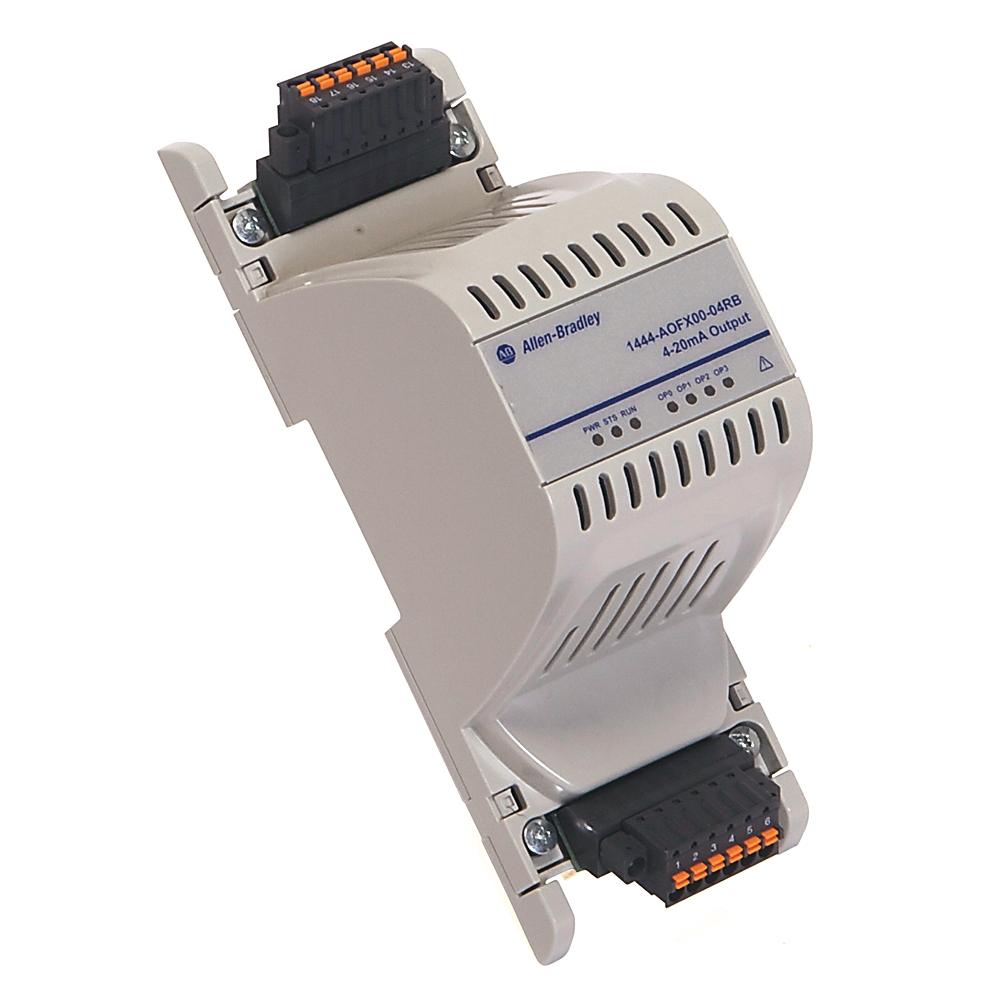
1444-aofx00-04rb
Expansion 4-20mA Output Module
Serial #:
This product has not been verified. Please register your product to confirm authenticity.
Lifecycle status:
Active
Lifecycle status:
Active
Technical Specifications
General
Electrical
Environmental
Fault Actions
Construction
Mechanical
Power
Channels
Indicators
Certification
Conformal Coating
Local Bus Function
Drawings
Documents
Certifications
Alternative Products
Technotes
| Number Of Outlet |
4
|
|---|
| Number of analogue inputs |
0
|
|---|---|
| Number of analogue outputs |
4
|
| Input, current |
False
|
| Input, voltage |
False
|
| Input, resistor |
False
|
| Input, resistance thermometer |
False
|
| Input, thermocouple |
False
|
| Input signal, configurable |
False
|
| Output, current |
True
|
| Output, voltage |
False
|
| Output signal configurable |
True
|
| Analogue inputs configurable |
False
|
| Analogue outputs configurable |
False
|
| Type of electric connection |
Screw-/spring clA connection
|
| Wire type |
Shielded on all signal ports
|
| Accuracy |
1% @ full scale
|
| Communication time-out, fixed |
1 s
|
| Conductor type |
Copper
|
| Wiring category |
2 - on signal ports
|
| Surrounding air temperature, max |
70 °C
|
|---|---|
| North American temperature code |
T4
|
| Operating temperature |
-25 °C
|
| Emissions |
IEC 61000-6-4
|
| ESD immunity |
6 kV contact discharges, 8 kV air discharges
|
| EFT/B immunity |
±2kV @ 5kHz on shielded signal ports
|
| Relative humidity |
5...95% noncondensing
|
| Conducted RF immunity |
10V rms with 1 kHz sine-wave 80% AM from 150 kHz...80 MHz
|
| Surge transient immunity |
±2 kV line-earth (CM) on shielded signal ports
|
| Radiated RF immunity |
10 V/m with 1 kHz sine-wave 80% AM from 80...2000 MHz, 10 V/m with 200 Hz 50% Pulse 100% AM @ 900 MHz, 1 V/m with 1 kHz sine-wave 80% AM from 2000...2700 MHz
|
| Operating temperature (spring type only), max |
105 °C
|
| Nonoperating temperature |
-40 °C
|
| Conductor/insulation temperature rating |
85 °C
|
| Output behavior on fault options |
No action
|
|---|---|
| Indication |
Update module status indicator
|
| Height |
With terminal base: 96 mm
|
|---|---|
| Width |
With terminal base: 54 mm
|
| Depth |
With terminal base: 158 mm
|
| Enclosure type rating |
None (open-style)
|
| Weight |
Without terminal base: 0.14 kg
|
|---|---|
| Vibration |
2.0 G @ 10…500 Hz
|
| Shock |
Operating: 15 G
|
| Stripping length |
9 mm
|
| Conductor cross section solid or stranded |
0.14
|
| Conductor crosssection stranded with ferrule without plastic sleeve |
0.25
|
| Conductor crosssection stranded with ferrule with plastic sleeve |
0.25
|
| Conductor cross section AWG/kcmil |
0.08
|
| Conductor UL/cUL AWG (screw type only) |
0.05 mm²
|
| Conductor UL/cUL AWG (spring type only) |
0.08 mm²
|
| Torque (screw type only) |
0.22 nm
|
| Voltage |
North American: 18...32V, max 8 A, limited voltage source
|
|---|---|
| Isolation voltage |
50V (continuous), basic insulation type between signal ports and AUX bus, No isolation between individual signal ports, Type tested at 707V DC @ 60s
|
| Dissipation |
3.6 W
|
| Consumption |
0.76 W
|
| Current |
18mA @ 24V (22...8mA @ 18...32V)
|
| Number of channels |
4
|
|---|---|
| Protection |
Insensitive to polarity
|
| Current output, max |
20 mA per output channel
|
| Not OK output |
Configurable: force low (2.9 mA), force high (>20 mA), hold current level
|
| Number of status indicators |
6
|
|---|---|
| Status indicator |
Power channel status (4), Local bus status
|
| IEC temperature code |
T4
|
|---|
| Conformal coating |
All printed circuit boards are conformal coated in accordance with IPC-A-610C and in compliance with: IPC-CC-830 B, UL508
|
|---|
| Communication |
A digital network that is used between a main module and its expansion modules is implemented on the local bus, Communication does not link main modules
|
|---|---|
| TTL signals |
Dual independent TTL signals, with tachom sensor status, are passed on the Local Bus, There can be only one tachom expansion module on a local bus, The TTL signal can serve up to six main modules
|
| Power |
Passes power from each main module (1444-DYN04-01RA) to its expansion modules, Power is not passed between main modules, When redundant power supplies are connected to a main module, only the voted power source is distributed to its expansion modules.
|
| Drawings | |
|---|---|
| 3D Dimension Drawings(STP) | Download (ZIP) |
| Product Drawing | Drawing (DXF) |
| Drawings |
|---|
| 3D Dimension Drawings(STP) Download (ZIP) |
| Product Drawing Drawing (DXF) |
| General | Publication |
|---|---|
| Product Cutsheet | -- |
| Technical Data | Publication |
|---|---|
| 1444-td001_-en-p | 1444-TD001 |
| User Manual | Publication |
|---|---|
| 1444-um001_-en-p | 1444-UM001 |
Looking for more documentation?
Find curated technical documentation for this product in the Technical Documentation Center, or search our full Literature Library.
Visit the Technical Documentation Center
Search the Literature Library
- China CCC
- IECEx Scheme
- ATEX
- UK EX CERTIFICATE
- MOROCCO DOC
This product was certified with the above certifications as of {}. Products sold before or after this date might carry different certifications. Please review the product label to check for the certifications your specific product carries.
Items Per Page:
| Technotes |
|---|
Looking for more Technotes?
Find questions and answers from Rockwell Automation technical experts for this product in our Knowledgebase.
Search Knowledgebase
Technical Specifications
| Number Of Outlet |
4
|
|---|
| Number of analogue inputs |
0
|
|---|---|
| Number of analogue outputs |
4
|
| Input, current |
False
|
| Input, voltage |
False
|
| Input, resistor |
False
|
| Input, resistance thermometer |
False
|
| Input, thermocouple |
False
|
| Input signal, configurable |
False
|
| Output, current |
True
|
| Output, voltage |
False
|
| Output signal configurable |
True
|
| Analogue inputs configurable |
False
|
| Analogue outputs configurable |
False
|
| Type of electric connection |
Screw-/spring clA connection
|
| Wire type |
Shielded on all signal ports
|
| Accuracy |
1% @ full scale
|
| Communication time-out, fixed |
1 s
|
| Conductor type |
Copper
|
| Wiring category |
2 - on signal ports
|
| Surrounding air temperature, max |
70 °C
|
|---|---|
| North American temperature code |
T4
|
| Operating temperature |
-25 °C
|
| Emissions |
IEC 61000-6-4
|
| ESD immunity |
6 kV contact discharges, 8 kV air discharges
|
| EFT/B immunity |
±2kV @ 5kHz on shielded signal ports
|
| Relative humidity |
5...95% noncondensing
|
| Conducted RF immunity |
10V rms with 1 kHz sine-wave 80% AM from 150 kHz...80 MHz
|
| Surge transient immunity |
±2 kV line-earth (CM) on shielded signal ports
|
| Radiated RF immunity |
10 V/m with 1 kHz sine-wave 80% AM from 80...2000 MHz, 10 V/m with 200 Hz 50% Pulse 100% AM @ 900 MHz, 1 V/m with 1 kHz sine-wave 80% AM from 2000...2700 MHz
|
| Operating temperature (spring type only), max |
105 °C
|
| Nonoperating temperature |
-40 °C
|
| Conductor/insulation temperature rating |
85 °C
|
| Output behavior on fault options |
No action
|
|---|---|
| Indication |
Update module status indicator
|
| Height |
With terminal base: 96 mm
|
|---|---|
| Width |
With terminal base: 54 mm
|
| Depth |
With terminal base: 158 mm
|
| Enclosure type rating |
None (open-style)
|
| Weight |
Without terminal base: 0.14 kg
|
|---|---|
| Vibration |
2.0 G @ 10…500 Hz
|
| Shock |
Operating: 15 G
|
| Stripping length |
9 mm
|
| Conductor cross section solid or stranded |
0.14
|
| Conductor crosssection stranded with ferrule without plastic sleeve |
0.25
|
| Conductor crosssection stranded with ferrule with plastic sleeve |
0.25
|
| Conductor cross section AWG/kcmil |
0.08
|
| Conductor UL/cUL AWG (screw type only) |
0.05 mm²
|
| Conductor UL/cUL AWG (spring type only) |
0.08 mm²
|
| Torque (screw type only) |
0.22 nm
|
| Voltage |
North American: 18...32V, max 8 A, limited voltage source
|
|---|---|
| Isolation voltage |
50V (continuous), basic insulation type between signal ports and AUX bus, No isolation between individual signal ports, Type tested at 707V DC @ 60s
|
| Dissipation |
3.6 W
|
| Consumption |
0.76 W
|
| Current |
18mA @ 24V (22...8mA @ 18...32V)
|
| Number of channels |
4
|
|---|---|
| Protection |
Insensitive to polarity
|
| Current output, max |
20 mA per output channel
|
| Not OK output |
Configurable: force low (2.9 mA), force high (>20 mA), hold current level
|
| Number of status indicators |
6
|
|---|---|
| Status indicator |
Power channel status (4), Local bus status
|
| IEC temperature code |
T4
|
|---|
| Conformal coating |
All printed circuit boards are conformal coated in accordance with IPC-A-610C and in compliance with: IPC-CC-830 B, UL508
|
|---|
| Communication |
A digital network that is used between a main module and its expansion modules is implemented on the local bus, Communication does not link main modules
|
|---|---|
| TTL signals |
Dual independent TTL signals, with tachom sensor status, are passed on the Local Bus, There can be only one tachom expansion module on a local bus, The TTL signal can serve up to six main modules
|
| Power |
Passes power from each main module (1444-DYN04-01RA) to its expansion modules, Power is not passed between main modules, When redundant power supplies are connected to a main module, only the voted power source is distributed to its expansion modules.
|
Drawings
| Drawings | |
|---|---|
| 3D Dimension Drawings(STP) | Download (ZIP) |
| Product Drawing | Drawing (DXF) |
| Drawings |
|---|
| 3D Dimension Drawings(STP) Download (ZIP) |
| Product Drawing Drawing (DXF) |
Documents
|
Product Cutsheet
General
-- |
|
1444-td001_-en-p
Technical Data
1444-TD001 |
|
1444-um001_-en-p
User Manual
1444-UM001 |
| General | Publication |
|---|---|
| Product Cutsheet | -- |
| Technical Data | Publication |
| 1444-td001_-en-p | 1444-TD001 |
| User Manual | Publication |
| 1444-um001_-en-p | 1444-UM001 |
Looking for more documentation?
Find curated technical documentation for this product in the Technical Documentation Center, or search our full Literature Library.
Visit the Technical Documentation Center
Search the Literature Library
Certifications
- China CCC
- IECEx Scheme
- ATEX
- UK EX CERTIFICATE
- MOROCCO DOC
This product was certified with the above certifications as of {}. Products sold before or after this date might carry different certifications. Please review the product label to check for the certifications your specific product carries.
Alternative Products
Items Per Page:
Technotes
| Technotes |
|---|
Looking for more Technotes?
Find questions and answers from Rockwell Automation technical experts for this product in our Knowledgebase.
Search Knowledgebase
Expansion 4-20mA Output Module
1444-aofx00-04rb
Close
Print
Copyright ©2026 Rockwell Automation, Inc.