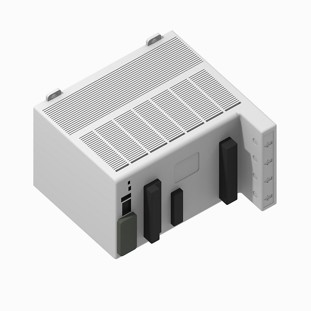
Powermonitor 5000 Base Quality Meter
| Unique Product Identifier |
1426-m5e
|
|---|---|
| UPC |
612598886210
|
| Estimated Lead Time |
5 days
|
| Standard Warranty Duration |
1 year See details |
| Country of Origin |
Malaysia
|
| EU Importer Address |
Rockwell Automation N.V |
| EU Authorized Representative Address |
Rockwell Automation N.V |
The information provided by Rockwell Automation on www.rockwellautomation.com (the “Site”) is for demonstration purposes only and may be incomplete or inaccurate. All information is provided “as is”, and Rockwell Automation makes no representations or warranties of any kind, express or implied, regarding the accuracy, adequacy, validity, reliability, or completeness of any information on the Site. Use of this information is at your own risk.
| Accuracy |
0.20%
|
|---|---|
| Alarm |
True
|
| Application |
Power Management/Quality m
|
| Communications |
EtherNet/IP
|
| Frequency Rating |
40-75Hz
|
| Interface |
Webpage
|
| Metering Voltage |
600VLL AC
|
| Output |
4 Digital Relays
|
| Vibration |
2 G
|
|---|---|
| Shock |
50 G, nonoperating
|
| Dielectric withstand |
UL61010, EN61010
|
| Storage temperature |
-40 to 85 °C
|
| Operating temperature |
-20 to 70 °C
|
| Altitude |
2000 m, max
|
| Installation location |
Indoor use only
|
| Humidity |
5...95% noncondensing
|
| Height |
132 mm
|
|---|---|
| Width |
185 mm
|
| Control power and ground wiring terminals |
• 120...240V AC @ 50/60Hz, or 120...240V DC • 24V DC
|
| Virtual wiring correction indicator |
Use current transformers (CTs) to connect to power system
|
| Voltage sensing wiring terminals |
• Direct connect to up to 690V AC 3-phase line to line • Maximum nominal line to ground voltage 690 • Use potential transformers (PTs) for higher voltages • Neutral voltage and ground voltage connections
|
| Device status indicators |
• Device status - OFF: No control power - Flashing GREEN/RED: Self-test - Flashing GREEN: Power monitor has not been configured - GREEN: Power monitor is running - Flashing RED: Power monitor has detected a recoverable minor fault - RED: Power monitor has detected a non-recoverable major fault
|
| Ethernet network port - standard RJ45 jack with status indicators |
Ethernet port hardware is included on all models. These protocols and functions are supported: • EtherNet/IP™ network • HTML web page for configuration and data access Ethernet indicators • LNK indicator - Solid GREEN: IP link established - Off: No link established • ACT indicator - Flashing YELLOW: Data present on Ethernet port - Off: No data activity present
|
| USB host port |
USB standard A receptacle. Not used in this model.
|
| Power |
•Power status - OFF: no control power - GREEN: control power is present
|
| Current sensing wiring terminals |
Nominal input current 5 A, Use current transformers (CTs) to connect to power system
|
| Configuration lock switch |
When enabled, this switch helps prevent changes in configuration that can affect revenue accuracy.
|
| USB device port |
The USB device port is a USB mini-B receptacle that accepts standard USB mini-B plugs, for connection to a host device, such as a notebook computer.
|
| Status input, KYZ output, and control relay wiring terminals |
• Four internally powered (24V DC) status inputs • Status input 2 can be used for demand period synchronization • KYZ DPDT solid-state relay for signaling use • Three DPDT control relays
|
| Network status indicators |
• Network status (Native Ethernet port) - OFF: No control power - Flashing GREEN/RED: Self-test - Flashing GREEN: No CIP connection - Solid GREEN: CIP connection established - Flashing RED: CIP connection timed out - Solid RED: Duplicate IP address detected
|
| IC rating class |
UL 508, CSA 22.2 @ DC: Q300
|
|---|---|
| Resistive load switching |
10A @ 24V DC, maximum
|
| Load switching |
100mA @ 5V AC, 50/60 Hz, RMS, minimum
|
| Motor load switching |
1/3HP @ 125V AC, 50/60 Hz, RMS, maximum
|
| Make values |
(Inductive load) 30A @ 120V AC, 50/60 Hz, RMS, maximum
|
| Break values |
(Inductive load) 0.55A @ 125V DC, maximum
|
| Crest factor |
V-V, V-N, and I, per phase: Yes
|
|---|---|
| Reactive energy (kVARh) |
True
|
| Frequency |
Nominal: 60 Hz
|
| Real energy (kWh) |
True
|
| Reactive power (kVAR) |
True
|
| Real power (kW) |
True
|
| Apparent power (kVA) |
True
|
| Real power demand (kW) |
True
|
| Reactive power demand (kVAR) |
True
|
| Apparent power demand (kVA) |
True
|
| Demand power factor |
True
|
| Projected kW demand |
True
|
| Projected kVAR demand |
True
|
| Projected kVA demand |
True
|
| Voltage unbalance |
True
|
| Current unbalance |
True
|
| Voltage, L-L and L-N |
True
|
| Current per phase and total |
True
|
| Symmetrical component analysis |
True
|
| True power factor per phase and total |
True
|
| Displacement power factor per phase and total |
True
|
| Apparent energy (kVAh) |
True
|
| Demand, amps |
True
|
| Projected amps demand |
True
|
| Current consumption |
True
|
| Control power |
12VA @ 24V DC
|
|---|---|
| Current sense inputs: I1, I2, I3 |
Accuracy: ±0.1% @ 25°C 50/60 Hz unity power factor
|
| Status inputs |
True
|
|---|---|
| Configurable via webpage |
True
|
| CIP energy object |
True
|
| Security |
True
|
| Wiring diagnostics |
True
|
| Virtual wiring correction |
True
|
| Network time synchronization |
True
|
| Network demand synchronization |
True
|
| IEEE 1588 precision time protocol |
True
|
| Pulse (digital) output (relay and KYZ) |
True
|
| Setpoint programming |
True
|
| Sag and swell detection |
True
|
| Web page |
True
|
| K-factor |
True
|
| Revenue accuracy |
True
|
| Total harmonic distortion (THD) |
True
|
| Control power |
12VA @ 24V DC
|
|---|---|
| Current sense inputs: I1, I2, I3 |
Accuracy: ±0.1% @ 25°C 50/60 Hz unity power factor
|
| Power functions |
• ANSI C12.20 -2010 class 0.2 clause 5.5.4 • EN 62053-22 -2003 class 0.2 accuracy clause 8
|
|---|---|
| Demand functions |
• ANSI C12.20 -2010 class 0.2 clause 5.5.4 • EN 62053-22 -2003 class 0.2 accuracy clause 8
|
| Metering update rates |
One update per line cycle, 1024 sAles per cycle per channel
|
| VG |
Connect to power system earth ground only, This connection is a functional ground.
|
| Energy functions |
• ANSI C12.20 -2010 class 0.2 clause 5.5.4 • EN 62053-22 -2003 class 0.2 accuracy clause 8
|
| Description |
PowerMonitor 5000 M5 unit with native ethernet communication network
|
|---|---|
| Ampere meter |
True
|
| Blind power meter |
True
|
| Frequency meter |
True
|
| Pulse counter |
True
|
| Voltmeter |
True
|
| Effective power measurement device |
True
|
| Depth |
178 mm
|
|---|
| Time of use log |
True
|
|---|---|
| Energy log |
True
|
| Minimum/maximum log |
True
|
| Load factor log |
True
|
| Alarm log |
True
|
| Data log |
True
|
| Event log |
True
|
| Setpoint log |
True
|
| EtherNet/IP |
True
|
|---|
| Drawings | |
|---|---|
| 2D Drawing (PDF) | Download (PDF) |
| 3 DImensional Drawing (PDF) | Download (PDF) |
| 3D STEP Model (STP) | Download (ZIP) |
| Product Drawing | Drawing (DXF) |
| Drawings |
|---|
| 2D Drawing (PDF) Download (PDF) |
| 3 DImensional Drawing (PDF) Download (PDF) |
| 3D STEP Model (STP) Download (ZIP) |
| Product Drawing Drawing (DXF) |
| General | Publication |
|---|---|
| Product Cutsheet | -- |
| PowerMonitor 5000 Product Profile | 1426-PP001 |
| PowerMonitor 5000 USB Driver Installation and Configuration Instructions | 1426-IN001 |
| User Manual | Publication |
|---|---|
| 1426-um001_-en-p | 1426-UM001 |
- Australian RCM
This product was certified with the above certifications as of {}. Products sold before or after this date might carry different certifications. Please review the product label to check for the certifications your specific product carries.
| Technotes |
|---|
Overview
| Unique Product Identifier |
1426-m5e
|
|---|---|
| UPC |
612598886210
|
| Estimated Lead Time |
5 days
|
| Standard Warranty Duration |
1 year See details |
| Country of Origin |
Malaysia
|
| EU Importer Address |
Rockwell Automation N.V |
| EU Authorized Representative Address |
Rockwell Automation N.V |
The information provided by Rockwell Automation on www.rockwellautomation.com (the “Site”) is for demonstration purposes only and may be incomplete or inaccurate. All information is provided “as is”, and Rockwell Automation makes no representations or warranties of any kind, express or implied, regarding the accuracy, adequacy, validity, reliability, or completeness of any information on the Site. Use of this information is at your own risk.
Technical Specifications
| Accuracy |
0.20%
|
|---|---|
| Alarm |
True
|
| Application |
Power Management/Quality m
|
| Communications |
EtherNet/IP
|
| Frequency Rating |
40-75Hz
|
| Interface |
Webpage
|
| Metering Voltage |
600VLL AC
|
| Output |
4 Digital Relays
|
| Vibration |
2 G
|
|---|---|
| Shock |
50 G, nonoperating
|
| Dielectric withstand |
UL61010, EN61010
|
| Storage temperature |
-40 to 85 °C
|
| Operating temperature |
-20 to 70 °C
|
| Altitude |
2000 m, max
|
| Installation location |
Indoor use only
|
| Humidity |
5...95% noncondensing
|
| Height |
132 mm
|
|---|---|
| Width |
185 mm
|
| Control power and ground wiring terminals |
• 120...240V AC @ 50/60Hz, or 120...240V DC • 24V DC
|
| Virtual wiring correction indicator |
Use current transformers (CTs) to connect to power system
|
| Voltage sensing wiring terminals |
• Direct connect to up to 690V AC 3-phase line to line • Maximum nominal line to ground voltage 690 • Use potential transformers (PTs) for higher voltages • Neutral voltage and ground voltage connections
|
| Device status indicators |
• Device status - OFF: No control power - Flashing GREEN/RED: Self-test - Flashing GREEN: Power monitor has not been configured - GREEN: Power monitor is running - Flashing RED: Power monitor has detected a recoverable minor fault - RED: Power monitor has detected a non-recoverable major fault
|
| Ethernet network port - standard RJ45 jack with status indicators |
Ethernet port hardware is included on all models. These protocols and functions are supported: • EtherNet/IP™ network • HTML web page for configuration and data access Ethernet indicators • LNK indicator - Solid GREEN: IP link established - Off: No link established • ACT indicator - Flashing YELLOW: Data present on Ethernet port - Off: No data activity present
|
| USB host port |
USB standard A receptacle. Not used in this model.
|
| Power |
•Power status - OFF: no control power - GREEN: control power is present
|
| Current sensing wiring terminals |
Nominal input current 5 A, Use current transformers (CTs) to connect to power system
|
| Configuration lock switch |
When enabled, this switch helps prevent changes in configuration that can affect revenue accuracy.
|
| USB device port |
The USB device port is a USB mini-B receptacle that accepts standard USB mini-B plugs, for connection to a host device, such as a notebook computer.
|
| Status input, KYZ output, and control relay wiring terminals |
• Four internally powered (24V DC) status inputs • Status input 2 can be used for demand period synchronization • KYZ DPDT solid-state relay for signaling use • Three DPDT control relays
|
| Network status indicators |
• Network status (Native Ethernet port) - OFF: No control power - Flashing GREEN/RED: Self-test - Flashing GREEN: No CIP connection - Solid GREEN: CIP connection established - Flashing RED: CIP connection timed out - Solid RED: Duplicate IP address detected
|
| IC rating class |
UL 508, CSA 22.2 @ DC: Q300
|
|---|---|
| Resistive load switching |
10A @ 24V DC, maximum
|
| Load switching |
100mA @ 5V AC, 50/60 Hz, RMS, minimum
|
| Motor load switching |
1/3HP @ 125V AC, 50/60 Hz, RMS, maximum
|
| Make values |
(Inductive load) 30A @ 120V AC, 50/60 Hz, RMS, maximum
|
| Break values |
(Inductive load) 0.55A @ 125V DC, maximum
|
| Crest factor |
V-V, V-N, and I, per phase: Yes
|
|---|---|
| Reactive energy (kVARh) |
True
|
| Frequency |
Nominal: 60 Hz
|
| Real energy (kWh) |
True
|
| Reactive power (kVAR) |
True
|
| Real power (kW) |
True
|
| Apparent power (kVA) |
True
|
| Real power demand (kW) |
True
|
| Reactive power demand (kVAR) |
True
|
| Apparent power demand (kVA) |
True
|
| Demand power factor |
True
|
| Projected kW demand |
True
|
| Projected kVAR demand |
True
|
| Projected kVA demand |
True
|
| Voltage unbalance |
True
|
| Current unbalance |
True
|
| Voltage, L-L and L-N |
True
|
| Current per phase and total |
True
|
| Symmetrical component analysis |
True
|
| True power factor per phase and total |
True
|
| Displacement power factor per phase and total |
True
|
| Apparent energy (kVAh) |
True
|
| Demand, amps |
True
|
| Projected amps demand |
True
|
| Current consumption |
True
|
| Control power |
12VA @ 24V DC
|
|---|---|
| Current sense inputs: I1, I2, I3 |
Accuracy: ±0.1% @ 25°C 50/60 Hz unity power factor
|
| Status inputs |
True
|
|---|---|
| Configurable via webpage |
True
|
| CIP energy object |
True
|
| Security |
True
|
| Wiring diagnostics |
True
|
| Virtual wiring correction |
True
|
| Network time synchronization |
True
|
| Network demand synchronization |
True
|
| IEEE 1588 precision time protocol |
True
|
| Pulse (digital) output (relay and KYZ) |
True
|
| Setpoint programming |
True
|
| Sag and swell detection |
True
|
| Web page |
True
|
| K-factor |
True
|
| Revenue accuracy |
True
|
| Total harmonic distortion (THD) |
True
|
| Control power |
12VA @ 24V DC
|
|---|---|
| Current sense inputs: I1, I2, I3 |
Accuracy: ±0.1% @ 25°C 50/60 Hz unity power factor
|
| Power functions |
• ANSI C12.20 -2010 class 0.2 clause 5.5.4 • EN 62053-22 -2003 class 0.2 accuracy clause 8
|
|---|---|
| Demand functions |
• ANSI C12.20 -2010 class 0.2 clause 5.5.4 • EN 62053-22 -2003 class 0.2 accuracy clause 8
|
| Metering update rates |
One update per line cycle, 1024 sAles per cycle per channel
|
| VG |
Connect to power system earth ground only, This connection is a functional ground.
|
| Energy functions |
• ANSI C12.20 -2010 class 0.2 clause 5.5.4 • EN 62053-22 -2003 class 0.2 accuracy clause 8
|
| Description |
PowerMonitor 5000 M5 unit with native ethernet communication network
|
|---|---|
| Ampere meter |
True
|
| Blind power meter |
True
|
| Frequency meter |
True
|
| Pulse counter |
True
|
| Voltmeter |
True
|
| Effective power measurement device |
True
|
| Depth |
178 mm
|
|---|
| Time of use log |
True
|
|---|---|
| Energy log |
True
|
| Minimum/maximum log |
True
|
| Load factor log |
True
|
| Alarm log |
True
|
| Data log |
True
|
| Event log |
True
|
| Setpoint log |
True
|
| EtherNet/IP |
True
|
|---|
Drawings
| Drawings | |
|---|---|
| 2D Drawing (PDF) | Download (PDF) |
| 3 DImensional Drawing (PDF) | Download (PDF) |
| 3D STEP Model (STP) | Download (ZIP) |
| Product Drawing | Drawing (DXF) |
| Drawings |
|---|
| 2D Drawing (PDF) Download (PDF) |
| 3 DImensional Drawing (PDF) Download (PDF) |
| 3D STEP Model (STP) Download (ZIP) |
| Product Drawing Drawing (DXF) |
Documents
|
Product Cutsheet
General
-- |
|
PowerMonitor 5000 Product Profile
General
1426-PP001 |
|
PowerMonitor 5000 USB Driver Installation and Configuration Instructions
General
1426-IN001 |
|
1426-um001_-en-p
User Manual
1426-UM001 |
| General | Publication |
|---|---|
| Product Cutsheet | -- |
| PowerMonitor 5000 Product Profile | 1426-PP001 |
| PowerMonitor 5000 USB Driver Installation and Configuration Instructions | 1426-IN001 |
| User Manual | Publication |
| 1426-um001_-en-p | 1426-UM001 |
Certifications
- Australian RCM
This product was certified with the above certifications as of {}. Products sold before or after this date might carry different certifications. Please review the product label to check for the certifications your specific product carries.
Accessories
Technotes
| Technotes |
|---|