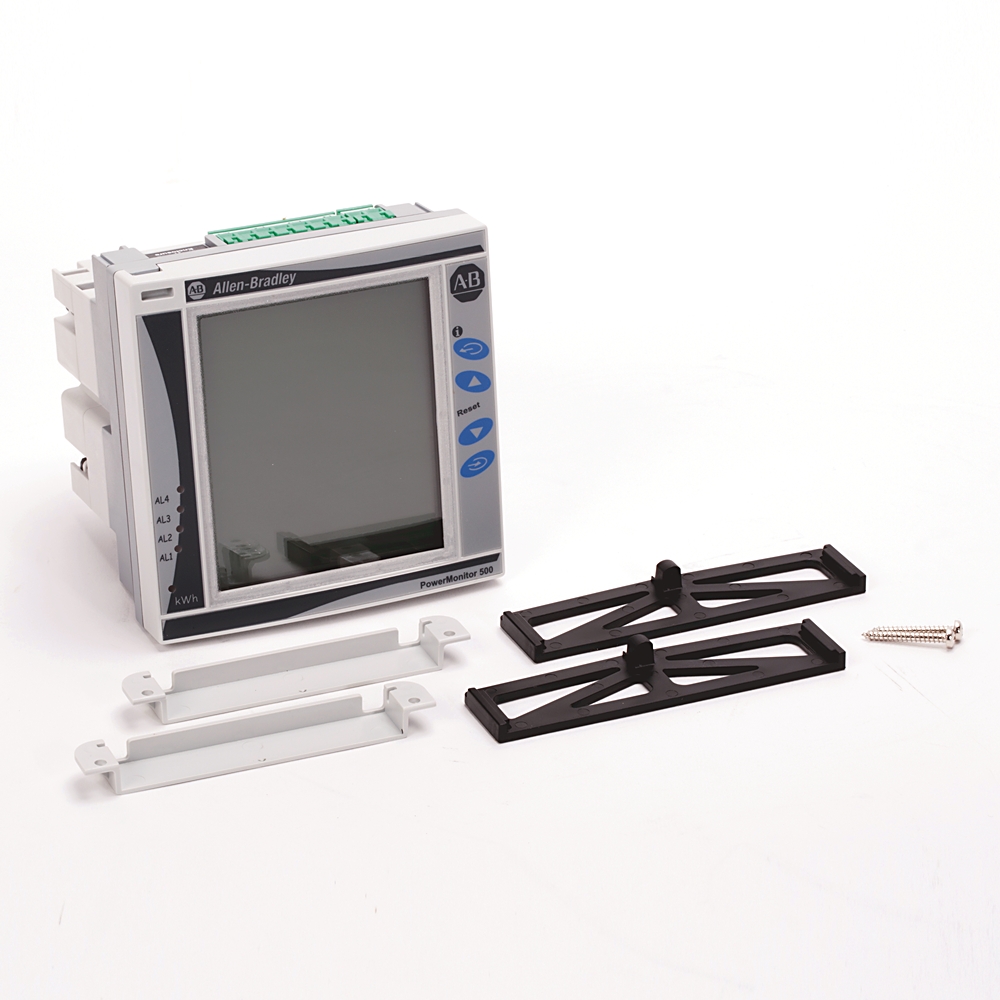
1420-V2A
Powermonitor 500 Power Meter
Serial #:
This product has not been verified. Please {} to confirm authenticity.
register your product
Lifecycle status:
Active
Description
PowerMonitor 500, 600V AC, 2 Analog Outputs
1420-V2A
Powermonitor 500 Power Meter
Serial #:
This product has not been verified. Please {} to confirm authenticity.
register your product
Lifecycle status:
Active
Description
PowerMonitor 500, 600V AC, 2 Analog Outputs
Overview
Electrical & Connectivity
General Features
Inputs & Outputs (I/O)
Standard Compliance
Power & Electrical Characteristics
Technical Specifications
Input/Output Specifications
General Specifications
Measurement & Parameters
Compliance & Environment
Environmental Operating Conditions
Physical Characteristics
Housing DIN
Drawings
Documents
Downloads
Accessories
Technotes
| Unique Product Identifier |
1420-V2A
|
|---|---|
| UPC |
885630236612
|
| Estimated Lead Time |
5 days
|
| Standard Warranty Duration |
1 year See details |
| Country of Origin |
Italy
|
| Accuracy |
1.00%
|
|---|---|
| Accuracy |
Voltage, nominal: 400V AC LN, 600V AC LL @ 25 °C ±5 °C, R.H. ≤ 60% @ 48...62Hz
|
| Alarm |
True
|
| An optional pair of 0 to 20 mA analog outputs |
True
|
| Class |
• Class 1 (kWh) according to EN62053-21, • Class B (kWh) according to EN50470-3, • Class 2 (kVARh) according to EN62053-23
|
| Communications |
None
|
| Configurable alarms |
True
|
| Configurable via software tool |
True
|
| Energy measurements (imported/exported) |
KWh and kVARh
|
| Energy value display |
Ten digits and the plus/minus sign
|
| Frequency Rating |
45-65Hz
|
| Front protection degree |
IP65, NEMA 4X, NEMA 12
|
| Height |
Front dimensions: 96 mm
|
| Interface |
Built-in LCD
|
| Metering values display |
Four rows with 4 digits
|
| Output |
2 Digital Relays
|
| Real-time clock function |
True
|
| Revenue grade energy measurements |
Per ANSI C12.1 Class 1.0, ANSI C12.1
|
| Run hours counter |
8+2 digits
|
| Single phase variables |
V(L-L), V(L-N), A(L), An (calculated), VA, W, VAR, power factor
|
| System and single phase average and maximum variables |
True
|
| Three-phase (system) variables |
V(L-L), V(L-N), A, VA, W, VAR, power factor, frequency
|
| Universal power supply |
120/240V AC 50/60 Hz or 120/240V DC
|
| Voltage rotation phase sequence |
True
|
| Width |
Front dimensions: 96 mm
|
| configurable virtual alarms |
Up to four
|
I/O Specifications
| Analog output (0 to 20 mA) |
True
|
|---|---|
| Current sensing |
Nominal: 5 A
|
| Voltage sensing |
Nominal: 400V AC LN, 600V AC LL Range: 160 to 480V AC LN RMS, 277 to 830V AC LL RMS
|
Output Signals
| Configuration |
By using the front keypad
|
|---|---|
| Load |
≤ 600 Ω
|
| Number of outputs |
2
|
| Range |
Maximum @ 0 to 20 mA
|
| Response time |
≤ 400 ms typical (filter excluded)
|
| Ripple |
≤ 1% (according to IEC 60688-1, EN 60688-1)
|
| Scaling factor |
Progmable within the whole range of retransmission, it allows the retransmission management of all values from 0 to 20 mA DC
|
| Signal retransmission |
The signal output can be connected to any instantaneous variable
|
| Total temperature drift |
≤ 500 ppm/°C
|
| Cable cross-section area |
2.5 mm2 AWG) max, Screw tightening torque: 0.4 N•m min/0.8 N•m max, Suggested screw tightening torque: 0.5 N•m
|
|---|---|
| Connections |
Screw-type
|
| Ampere meter |
True
|
|---|---|
| Blind power meter |
True
|
| Effective power measurement device |
True
|
| Frequency meter |
True
|
| Pulse counter |
True
|
| Voltmeter |
True
|
| Control power |
Range: 100 to 240V AC (48 to 62 Hz)
|
|---|---|
| Coupling type |
With CTs
|
| Current overloads |
6 A, at 50/60 Hz, Continuous
|
| Current range (by CT) |
5 A nominal (6 A maximum)
|
| Current type |
Galvanic insulation with built-in CTs
|
| Energy additional errors |
According to EN62053-21 ANSI C12.1, influence quantities Class B according to EN50470-3, EN62053-23
|
| Input impedance |
5(6)A, < 0.2VA
|
| Method |
True RMS measurements of distorted wave forms
|
| Rated inputs |
System type: 1, 2, or 3-phase
|
| Sampling rate |
3840 sAles/s at 60 Hz, 3200 sAles/s at 50 Hz
|
| Temperature drift |
≤ 200 ppm/°C
|
| Voltage (by direct connection or VT/PT) |
400/600V LL
|
| Voltage overloads |
2 × Vnom (where Vnom is the nominal voltage of the module), for 500 ms
|
| Current all models |
From 0.01 to 0.25 A: ±(1.0% of reading (RDG) + 2 digits From 0.25 to 6 A: ±(0.5% RDG +2 digits)
|
|---|---|
| Current sensing model |
Inominal: 5 A, Imaximum: 6A
|
| Line-line RMS |
Maximum @ 277 to 830V AC
|
| Line-line voltage |
In the range Vnom: ±(1.0% RDG +1 digit)
|
| Line-neutral RMS |
Maximum @ 160 to 480V AC
|
| Line-neutral voltage |
In the range Vnom: ±(0.5% RDG +1 digit)
|
| Real and apparent power |
From 0.05 to 0.25 A, PF 1: ±(2% RDG +1 digit) From 0.25 to 6A, PF 0.5L, PF1, PF 0.8C: ±(1.0% RDG+1 digit)
|
| Start up current |
5
|
Measurement Types & Capabilities
| Apparent power (kVA) |
True
|
|---|---|
| Apparent power consumption (kVAh) |
True
|
| Crest factor |
≤3 (15 A max peak)
|
| Current |
True
|
| Demand (kVA) |
True
|
| Demand (kVAR) |
True
|
| Demand (kW) |
True
|
| Demand power factor |
True
|
| Frequency |
Hz: Yes
|
| Power factor |
PF: Yes
|
| Reactive energy (kVARh) |
Class 2 according to EN62053-23, ANSI C12.1
|
| Reactive power (kVAR) |
True
|
| Reactive power consumption (kVARh) |
True
|
| Real energy (kWh) |
Class 1 according to EN62053-21, ANSI C12.1 Class B according to EN50470-3
|
| Real power (kW) |
True
|
| Real power consumption (kWh) |
True
|
| Voltage |
True
|
| Burst |
On current and voltage measuring inputs circuit: 4 kV
|
|---|---|
| Dielectric strength |
4 kV AC rms for 1 min
|
| EMC |
According to EN62052-11
|
| Electrostatic discharge |
15 kV air discharge
|
| Immunity to conducted disturbances |
10V/m from 150 KHz to 80 MHz
|
| Immunity to radiated electromagnetic fields |
Test without any current: 30V/m from 80 to 2000 MHz
|
| Installation category |
Cat. III (IEC60664, EN60664)
|
| Noise rejection CMRR |
100 dB, 48 to 62 Hz
|
| Operating temperature |
-25 to +40 °C (-13 to +104 °F) (R.H. from 0…90% noncondensing @ 40 °C) according to EN62053-21, EN50470-1 and EN62053- 23
|
| Radio frequency suppression |
According to CISPR 22
|
| Storage temperature |
-30 to +70 °C (-22 to +158 °F) (R.H.P178 < 90% noncondensing @ 40 °C) according to EN62053-21, EN50470-1 and EN62053- 23
|
| Surge |
On current and voltage measuring inputs circuit: 4 kV, on ‘L’ auxiliary power supply input: 1 kV
|
Housing DIN
| Depth behind panel |
Maximum @ 81.7 mm (3.2 in.)
|
|---|---|
| Dimensions (WxHxD) |
Module holder: 96 x 96 x 50 mm (3.78 x 3.78 x 1.97 in.), Digital and analog output type modules: 89.5 x 63 x 16 mm (3.52 x 2.48 x 0.63 in.), Serial and Ethernet Communication type modules: 89.5 x 63 x 20 mm (3.52 x 2.48 x 0.79 in.)
|
| Material |
ABS, self-extinguishing: UL 94 V-0
|
| Mounting |
Panel mounting
|
| Pollution degree |
2
|
| Screw terminals |
IP20
|
| Weight |
Approx 400 g (0.88 lb) (packing included)
|
| Drawings | |
|---|---|
| 3D STEP Model (STP) | Download (ZIP) |
| 2D Drawing (PDF) | Download (PDF) |
| 3 Dimensional Drawing (PDF) | Download (PDF) |
| Product Drawing | Drawing (DXF) |
| Drawings |
|---|
| 3D STEP Model (STP) Download (ZIP) |
| 2D Drawing (PDF) Download (PDF) |
| 3 Dimensional Drawing (PDF) Download (PDF) |
| Product Drawing Drawing (DXF) |
Click the Download CAD button below to view all file formats available for download.
Sign in to your Rockwell Automation account to view and download technical drawings.
Sign In
| General | Publication |
|---|---|
| Product Cutsheet | -- |
| User Manual | Publication |
|---|---|
| 1420-um001_-en-p | 1420-UM001 |
Looking for more documentation?
Find curated technical documentation for this product in the Technical Documentation Center, or search our full Literature Library.
Visit the Technical Documentation Center
Search the Literature Library
Version:
Release notes
| Accessory Files | Size | Notes | |
|---|---|---|---|
|
|
1420-Vx-xxx Configuration Software | 743 KB | |
|
|
1420-Vx-xxx Configuration Software | 743 KB | |
|
|
1420-Vx-xxx Configuration Software | 743 KB | |
|
|
1420-Vx-xxx Configuration Software | 743 KB | |
|
|
1420-Vx-xxx Configuration Software | 743 KB | |
| EDS - Electronic Data Sheet Files | Size | Notes | |
|
|
EDS files for 1420-Vx-ENT (multi) | 113 KB | |
|
|
EDS files for PEM Products Family (multi) | 430 KB | |
|
|
EDS files for 1420-Vx-ENT (multi) | 113 KB | |
|
|
EDS files for PEM Products Family (multi) | 430 KB | |
|
|
EDS files for 1420-Vx-ENT (multi) | 113 KB | |
|
|
EDS files for PEM Products Family (multi) | 430 KB | |
|
|
EDS files for 1420-Vx-ENT (multi) | 113 KB | |
|
|
EDS files for PEM Products Family (multi) | 430 KB | |
|
|
EDS files for 1420-Vx-ENT (multi) | 113 KB | |
|
|
EDS files for PEM Products Family (multi) | 430 KB | |
| Firmware | Size | Notes | |
|
|
Firmware for 1420-Vx-ENT v5.002 | 908 KB | |
|
|
Firmware for 1420-Vx-ENT v5.001 | 908 KB | |
|
|
Firmware for PowerMonitor 500 1420-Vx-ENT V4.002 | 882 KB | |
|
|
Firmware for 1420-Vx-ENT v4.001 | 874 KB | |
Looking for more Downloads?
Find product downloads in Rockwell Automation Product Compatibility and Download Center.
Search PCDC
Items Per Page:
| Technotes |
|---|
Looking for more Technotes?
Find questions and answers from Rockwell Automation technical experts for this product in our Knowledgebase.
Search Knowledgebase
Overview
| Unique Product Identifier |
1420-V2A
|
|---|---|
| UPC |
885630236612
|
| Estimated Lead Time |
5 days
|
| Standard Warranty Duration |
1 year See details |
| Country of Origin |
Italy
|
Electrical & Connectivity
| Accuracy |
1.00%
|
|---|---|
| Accuracy |
Voltage, nominal: 400V AC LN, 600V AC LL @ 25 °C ±5 °C, R.H. ≤ 60% @ 48...62Hz
|
| Alarm |
True
|
| An optional pair of 0 to 20 mA analog outputs |
True
|
| Class |
• Class 1 (kWh) according to EN62053-21, • Class B (kWh) according to EN50470-3, • Class 2 (kVARh) according to EN62053-23
|
| Communications |
None
|
| Configurable alarms |
True
|
| Configurable via software tool |
True
|
| Energy measurements (imported/exported) |
KWh and kVARh
|
| Energy value display |
Ten digits and the plus/minus sign
|
| Frequency Rating |
45-65Hz
|
| Front protection degree |
IP65, NEMA 4X, NEMA 12
|
| Height |
Front dimensions: 96 mm
|
| Interface |
Built-in LCD
|
| Metering values display |
Four rows with 4 digits
|
| Output |
2 Digital Relays
|
| Real-time clock function |
True
|
| Revenue grade energy measurements |
Per ANSI C12.1 Class 1.0, ANSI C12.1
|
| Run hours counter |
8+2 digits
|
| Single phase variables |
V(L-L), V(L-N), A(L), An (calculated), VA, W, VAR, power factor
|
| System and single phase average and maximum variables |
True
|
| Three-phase (system) variables |
V(L-L), V(L-N), A, VA, W, VAR, power factor, frequency
|
| Universal power supply |
120/240V AC 50/60 Hz or 120/240V DC
|
| Voltage rotation phase sequence |
True
|
| Width |
Front dimensions: 96 mm
|
| configurable virtual alarms |
Up to four
|
I/O Specifications
| Analog output (0 to 20 mA) |
True
|
|---|---|
| Current sensing |
Nominal: 5 A
|
| Voltage sensing |
Nominal: 400V AC LN, 600V AC LL Range: 160 to 480V AC LN RMS, 277 to 830V AC LL RMS
|
Output Signals
| Configuration |
By using the front keypad
|
|---|---|
| Load |
≤ 600 Ω
|
| Number of outputs |
2
|
| Range |
Maximum @ 0 to 20 mA
|
| Response time |
≤ 400 ms typical (filter excluded)
|
| Ripple |
≤ 1% (according to IEC 60688-1, EN 60688-1)
|
| Scaling factor |
Progmable within the whole range of retransmission, it allows the retransmission management of all values from 0 to 20 mA DC
|
| Signal retransmission |
The signal output can be connected to any instantaneous variable
|
| Total temperature drift |
≤ 500 ppm/°C
|
| Cable cross-section area |
2.5 mm2 AWG) max, Screw tightening torque: 0.4 N•m min/0.8 N•m max, Suggested screw tightening torque: 0.5 N•m
|
|---|---|
| Connections |
Screw-type
|
| Ampere meter |
True
|
|---|---|
| Blind power meter |
True
|
| Effective power measurement device |
True
|
| Frequency meter |
True
|
| Pulse counter |
True
|
| Voltmeter |
True
|
Technical Specifications
| Control power |
Range: 100 to 240V AC (48 to 62 Hz)
|
|---|---|
| Coupling type |
With CTs
|
| Current overloads |
6 A, at 50/60 Hz, Continuous
|
| Current range (by CT) |
5 A nominal (6 A maximum)
|
| Current type |
Galvanic insulation with built-in CTs
|
| Energy additional errors |
According to EN62053-21 ANSI C12.1, influence quantities Class B according to EN50470-3, EN62053-23
|
| Input impedance |
5(6)A, < 0.2VA
|
| Method |
True RMS measurements of distorted wave forms
|
| Rated inputs |
System type: 1, 2, or 3-phase
|
| Sampling rate |
3840 sAles/s at 60 Hz, 3200 sAles/s at 50 Hz
|
| Temperature drift |
≤ 200 ppm/°C
|
| Voltage (by direct connection or VT/PT) |
400/600V LL
|
| Voltage overloads |
2 × Vnom (where Vnom is the nominal voltage of the module), for 500 ms
|
| Current all models |
From 0.01 to 0.25 A: ±(1.0% of reading (RDG) + 2 digits From 0.25 to 6 A: ±(0.5% RDG +2 digits)
|
|---|---|
| Current sensing model |
Inominal: 5 A, Imaximum: 6A
|
| Line-line RMS |
Maximum @ 277 to 830V AC
|
| Line-line voltage |
In the range Vnom: ±(1.0% RDG +1 digit)
|
| Line-neutral RMS |
Maximum @ 160 to 480V AC
|
| Line-neutral voltage |
In the range Vnom: ±(0.5% RDG +1 digit)
|
| Real and apparent power |
From 0.05 to 0.25 A, PF 1: ±(2% RDG +1 digit) From 0.25 to 6A, PF 0.5L, PF1, PF 0.8C: ±(1.0% RDG+1 digit)
|
| Start up current |
5
|
Measurement Types & Capabilities
| Apparent power (kVA) |
True
|
|---|---|
| Apparent power consumption (kVAh) |
True
|
| Crest factor |
≤3 (15 A max peak)
|
| Current |
True
|
| Demand (kVA) |
True
|
| Demand (kVAR) |
True
|
| Demand (kW) |
True
|
| Demand power factor |
True
|
| Frequency |
Hz: Yes
|
| Power factor |
PF: Yes
|
| Reactive energy (kVARh) |
Class 2 according to EN62053-23, ANSI C12.1
|
| Reactive power (kVAR) |
True
|
| Reactive power consumption (kVARh) |
True
|
| Real energy (kWh) |
Class 1 according to EN62053-21, ANSI C12.1 Class B according to EN50470-3
|
| Real power (kW) |
True
|
| Real power consumption (kWh) |
True
|
| Voltage |
True
|
Compliance & Environment
| Burst |
On current and voltage measuring inputs circuit: 4 kV
|
|---|---|
| Dielectric strength |
4 kV AC rms for 1 min
|
| EMC |
According to EN62052-11
|
| Electrostatic discharge |
15 kV air discharge
|
| Immunity to conducted disturbances |
10V/m from 150 KHz to 80 MHz
|
| Immunity to radiated electromagnetic fields |
Test without any current: 30V/m from 80 to 2000 MHz
|
| Installation category |
Cat. III (IEC60664, EN60664)
|
| Noise rejection CMRR |
100 dB, 48 to 62 Hz
|
| Operating temperature |
-25 to +40 °C (-13 to +104 °F) (R.H. from 0…90% noncondensing @ 40 °C) according to EN62053-21, EN50470-1 and EN62053- 23
|
| Radio frequency suppression |
According to CISPR 22
|
| Storage temperature |
-30 to +70 °C (-22 to +158 °F) (R.H.P178 < 90% noncondensing @ 40 °C) according to EN62053-21, EN50470-1 and EN62053- 23
|
| Surge |
On current and voltage measuring inputs circuit: 4 kV, on ‘L’ auxiliary power supply input: 1 kV
|
Physical Characteristics
Housing DIN
| Depth behind panel |
Maximum @ 81.7 mm (3.2 in.)
|
|---|---|
| Dimensions (WxHxD) |
Module holder: 96 x 96 x 50 mm (3.78 x 3.78 x 1.97 in.), Digital and analog output type modules: 89.5 x 63 x 16 mm (3.52 x 2.48 x 0.63 in.), Serial and Ethernet Communication type modules: 89.5 x 63 x 20 mm (3.52 x 2.48 x 0.79 in.)
|
| Material |
ABS, self-extinguishing: UL 94 V-0
|
| Mounting |
Panel mounting
|
| Pollution degree |
2
|
| Screw terminals |
IP20
|
| Weight |
Approx 400 g (0.88 lb) (packing included)
|
Drawings
| Drawings | |
|---|---|
| 3D STEP Model (STP) | Download (ZIP) |
| 2D Drawing (PDF) | Download (PDF) |
| 3 Dimensional Drawing (PDF) | Download (PDF) |
| Product Drawing | Drawing (DXF) |
| Drawings |
|---|
| 3D STEP Model (STP) Download (ZIP) |
| 2D Drawing (PDF) Download (PDF) |
| 3 Dimensional Drawing (PDF) Download (PDF) |
| Product Drawing Drawing (DXF) |
Click the Download CAD button below to view all file formats available for download.
Sign in to your Rockwell Automation account to view and download technical drawings.
Sign In
Documents
|
Product Cutsheet
General
-- |
|
1420-um001_-en-p
User Manual
1420-UM001 |
| General | Publication |
|---|---|
| Product Cutsheet | -- |
| User Manual | Publication |
| 1420-um001_-en-p | 1420-UM001 |
Looking for more documentation?
Find curated technical documentation for this product in the Technical Documentation Center, or search our full Literature Library.
Visit the Technical Documentation Center
Search the Literature Library
Downloads
Version:
Release notes
| Accessory Files | Size | Notes | |
|---|---|---|---|
|
|
1420-Vx-xxx Configuration Software | 743 KB | |
|
|
1420-Vx-xxx Configuration Software | 743 KB | |
|
|
1420-Vx-xxx Configuration Software | 743 KB | |
|
|
1420-Vx-xxx Configuration Software | 743 KB | |
|
|
1420-Vx-xxx Configuration Software | 743 KB | |
| EDS - Electronic Data Sheet Files | Size | Notes | |
|
|
EDS files for 1420-Vx-ENT (multi) | 113 KB | |
|
|
EDS files for PEM Products Family (multi) | 430 KB | |
|
|
EDS files for 1420-Vx-ENT (multi) | 113 KB | |
|
|
EDS files for PEM Products Family (multi) | 430 KB | |
|
|
EDS files for 1420-Vx-ENT (multi) | 113 KB | |
|
|
EDS files for PEM Products Family (multi) | 430 KB | |
|
|
EDS files for 1420-Vx-ENT (multi) | 113 KB | |
|
|
EDS files for PEM Products Family (multi) | 430 KB | |
|
|
EDS files for 1420-Vx-ENT (multi) | 113 KB | |
|
|
EDS files for PEM Products Family (multi) | 430 KB | |
| Firmware | Size | Notes | |
|
|
Firmware for 1420-Vx-ENT v5.002 | 908 KB | |
|
|
Firmware for 1420-Vx-ENT v5.001 | 908 KB | |
|
|
Firmware for PowerMonitor 500 1420-Vx-ENT V4.002 | 882 KB | |
|
|
Firmware for 1420-Vx-ENT v4.001 | 874 KB | |
Looking for more Downloads?
Find product downloads in Rockwell Automation Product Compatibility and Download Center.
Search PCDC
Accessories
Items Per Page:
Technotes
| Technotes |
|---|
Looking for more Technotes?
Find questions and answers from Rockwell Automation technical experts for this product in our Knowledgebase.
Search Knowledgebase
Multiple countries of origin based on manufacturing location
Powermonitor 500 Power Meter
1420-V2A
Close
Print

Copyright ©2026 Rockwell Automation, Inc.