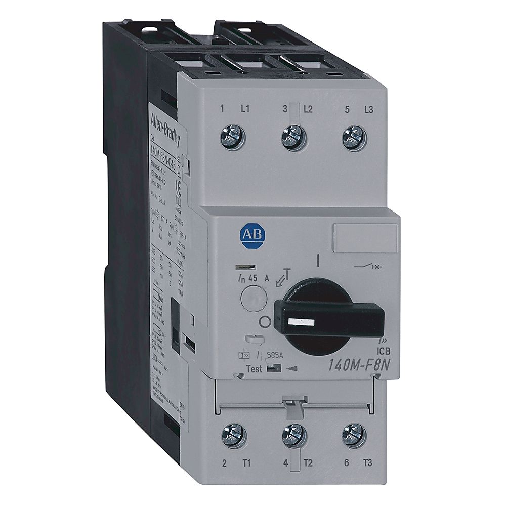
140M-F8N-C45-KN
Motor Circuit Protector Circuit-Breaker
Rockwell Automation announces that as of July 26, 2023, the Motor Circuit Protector Circuit-Breaker will be discontinued and no longer available for sale. Customers are encouraged to remove references to the affected product(s)
Discontinued Date:
July 26, 2023
Replacement Category:
Engineering Replacement
| Adj. Thermal Current Range (A) |
TheMaxRtgForMPCBs=630.0A @ 45A
|
|---|---|
| Circuit Breaker Type |
Motor Circuit Protector
|
| Number of poles |
3
|
|---|---|
| With integrated under voltage release |
False
|
| Rated short-circuit breaking capacity lcu at 400 V, 50 Hz |
65 kA
|
| Complete device with protection unit |
True
|
| Rated permanent current Iu |
45 A
|
| Rated voltage |
230 V
|
| Type of control element |
Turn button
|
| Magnetic release current per IEC |
585 A
|
| Magnetic trip current, nom |
585 A
|
| Rated operational current (Ie) per IEC |
45 A
|
| Rated frequency |
45 Hz
|
| Current range |
45 A
|
| Rated supply current (Ie) |
6.3 A
|
| Ultimate short circuit breaking capacity (Icu) per IEC |
65kA @ 400/415V AC
|
| Rated service short circuit breaking capacity (Ics) per IEC |
6kA @ 690V AC
|
| Hp rating, max |
40Hp @ 575V, 3-phase
|
| Rated insulation voltage (Ui) |
Rated 690V per IEC
|
| KW rating, max |
40 kW @ 690V (AC-3), 3-phase
|
| Switching of standard motors per IEC |
40 kW @ 690V (AC-3), 3-phase
|
| Back up fuse (gG, gL) current rating (if Icc ≥ Icu ) per IEC |
125A @ 500/525V AC
|
| Short circuit current (Type 2 coordination), max |
65kA @ 480V with 100-C IEC contactors
|
| Short circuit current for UL 508 Type E (Self-Protected) combination motor controller, max |
65 kA @ 480Y/277V with 100-C contactors
|
| Total power loss (Pv) for circuit breaker |
7…22 W @ rated load/operating temperature
|
| Electrical life cycle |
30000 ops (Ie maximum)
|
| Rated thermal current (Ith) |
6.3...45 A up to 60 °C (140 °F) ambient temperature
|
| Fuse or circuit breaker per NEC, max |
600 A, UL 60947-4-1-manual motor controller
|
| Fuse or circuit breaker rating per NEC, max |
600 A, UL 60947-4-1-manual motor controller with 100-C IEC contactors
|
| Rated impulse withstand voltage (Uimp) |
Main circuits (Uimp)/overvoltage category: 6 kV/III, 8 kV (disconnect)
|
| Short circuit current for group motor installation, max |
65kA @ 480V, UL 60947-4-1-manual motor controller with 100-C IEC contactors
|
| Short circuit current for motor disconnect, max |
65kA @ 480V, UL 60947-4-1-manual motor controller with 100-C IEC contactors
|
| Magnetic release current (±20 %) |
Fixed setting: 18…22 x Ie maximum (Ie maximum = maximum values of setting ranges) for T version
|
| Protection type |
Fixed magnetic only (13 x In)
|
| Motor drive integrated |
False
|
| With switched-off indicator |
False
|
| Motor drive optional |
True
|
| Position of connection for main current circuit |
Front side
|
| Type of electrical connection of main circuit |
Screw connection
|
| Switching frequency, max |
25 ops/h
|
| Phase loss protection |
Differential release
|
| Suitable for DIN rail (top hat rail) mounting |
False
|
|---|---|
| DIN rail (top hat rail) mounting optional |
True
|
| Degree of protection (IP) |
IP2X
|
| Weight |
782 lb
|
| Mechanical life operations |
30000 /h
|
| Breaking capacity |
High breaking capacity
|
| Vibration |
Ops (60068-2-6): 5 G
|
| Shock |
Transport (60068-2-27): 30 G/11 ms, OFF
|
| Factory option |
No circuit-breaker auxiliary or trip contacts
|
| Overload protection characteristics |
IEC 60947-4-1 motor protection
|
| Ambient storage temperature |
-40 °C
|
|---|---|
| Ambient operating temperature |
-25 °C
|
| Ambient temperature compensation |
-25 °C
|
| Site altitude |
To 2000 m N.N. (6561 ft)
|
| Dependence on temperature |
No reduction @ 60 °C (140 °F)
|
| Pollution degree |
3
|
| Climatic resistance |
Operating humidity/moisture heat (60068-2-3): 5...95% non-condensing
|
| Frame size |
Frame size F, 45 A
|
|---|---|
| Contactor size (Type 2 coordination), min |
100-C37 @ 600V with 100-C IEC contactors
|
| Contactor size, min |
100-C37, UL 60947-4-1-manual motor controller with 100-C IEC contactors
|
| Device construction |
Built-in device fixed built-in technique
|
| Utilization category |
Motor starter: AC-3 (IEC60947-4-1)
|
|---|
Sign in to your Rockwell Automation account to view and download technical drawings.
Sign In
| Type | Resource | Publication |
|---|---|---|
| Technical Data | 140m-td002_-en-p | 140M-TD002 |
Looking for more documentation?
Find curated technical documentation for this product in the Technical Documentation Center, or search our full Literature Library.
Search the Literature Library
- China CCC
This product was certified with the above certifications as of 2025-10-21. Products sold before or after this date might carry different certifications. Please review the product label to check for the certifications your specific product carries.
Looking for more Technotes?
Find questions and answers from Rockwell Automation technical experts for this product in our Knowledgebase.
Search Knowledgebase
Technical Specifications
| Adj. Thermal Current Range (A) |
TheMaxRtgForMPCBs=630.0A @ 45A
|
|---|---|
| Circuit Breaker Type |
Motor Circuit Protector
|
| Number of poles |
3
|
|---|---|
| With integrated under voltage release |
False
|
| Rated short-circuit breaking capacity lcu at 400 V, 50 Hz |
65 kA
|
| Complete device with protection unit |
True
|
| Rated permanent current Iu |
45 A
|
| Rated voltage |
230 V
|
| Type of control element |
Turn button
|
| Magnetic release current per IEC |
585 A
|
| Magnetic trip current, nom |
585 A
|
| Rated operational current (Ie) per IEC |
45 A
|
| Rated frequency |
45 Hz
|
| Current range |
45 A
|
| Rated supply current (Ie) |
6.3 A
|
| Ultimate short circuit breaking capacity (Icu) per IEC |
65kA @ 400/415V AC
|
| Rated service short circuit breaking capacity (Ics) per IEC |
6kA @ 690V AC
|
| Hp rating, max |
40Hp @ 575V, 3-phase
|
| Rated insulation voltage (Ui) |
Rated 690V per IEC
|
| KW rating, max |
40 kW @ 690V (AC-3), 3-phase
|
| Switching of standard motors per IEC |
40 kW @ 690V (AC-3), 3-phase
|
| Back up fuse (gG, gL) current rating (if Icc ≥ Icu ) per IEC |
125A @ 500/525V AC
|
| Short circuit current (Type 2 coordination), max |
65kA @ 480V with 100-C IEC contactors
|
| Short circuit current for UL 508 Type E (Self-Protected) combination motor controller, max |
65 kA @ 480Y/277V with 100-C contactors
|
| Total power loss (Pv) for circuit breaker |
7…22 W @ rated load/operating temperature
|
| Electrical life cycle |
30000 ops (Ie maximum)
|
| Rated thermal current (Ith) |
6.3...45 A up to 60 °C (140 °F) ambient temperature
|
| Fuse or circuit breaker per NEC, max |
600 A, UL 60947-4-1-manual motor controller
|
| Fuse or circuit breaker rating per NEC, max |
600 A, UL 60947-4-1-manual motor controller with 100-C IEC contactors
|
| Rated impulse withstand voltage (Uimp) |
Main circuits (Uimp)/overvoltage category: 6 kV/III, 8 kV (disconnect)
|
| Short circuit current for group motor installation, max |
65kA @ 480V, UL 60947-4-1-manual motor controller with 100-C IEC contactors
|
| Short circuit current for motor disconnect, max |
65kA @ 480V, UL 60947-4-1-manual motor controller with 100-C IEC contactors
|
| Magnetic release current (±20 %) |
Fixed setting: 18…22 x Ie maximum (Ie maximum = maximum values of setting ranges) for T version
|
| Protection type |
Fixed magnetic only (13 x In)
|
| Motor drive integrated |
False
|
| With switched-off indicator |
False
|
| Motor drive optional |
True
|
| Position of connection for main current circuit |
Front side
|
| Type of electrical connection of main circuit |
Screw connection
|
| Switching frequency, max |
25 ops/h
|
| Phase loss protection |
Differential release
|
| Suitable for DIN rail (top hat rail) mounting |
False
|
|---|---|
| DIN rail (top hat rail) mounting optional |
True
|
| Degree of protection (IP) |
IP2X
|
| Weight |
782 lb
|
| Mechanical life operations |
30000 /h
|
| Breaking capacity |
High breaking capacity
|
| Vibration |
Ops (60068-2-6): 5 G
|
| Shock |
Transport (60068-2-27): 30 G/11 ms, OFF
|
| Factory option |
No circuit-breaker auxiliary or trip contacts
|
| Overload protection characteristics |
IEC 60947-4-1 motor protection
|
| Ambient storage temperature |
-40 °C
|
|---|---|
| Ambient operating temperature |
-25 °C
|
| Ambient temperature compensation |
-25 °C
|
| Site altitude |
To 2000 m N.N. (6561 ft)
|
| Dependence on temperature |
No reduction @ 60 °C (140 °F)
|
| Pollution degree |
3
|
| Climatic resistance |
Operating humidity/moisture heat (60068-2-3): 5...95% non-condensing
|
| Frame size |
Frame size F, 45 A
|
|---|---|
| Contactor size (Type 2 coordination), min |
100-C37 @ 600V with 100-C IEC contactors
|
| Contactor size, min |
100-C37, UL 60947-4-1-manual motor controller with 100-C IEC contactors
|
| Device construction |
Built-in device fixed built-in technique
|
| Utilization category |
Motor starter: AC-3 (IEC60947-4-1)
|
|---|
Drawings
Sign in to your Rockwell Automation account to view and download technical drawings.
Sign In
Documents
|
140m-td002_-en-p
Technical Data
140M-TD002 |
| Type | Resource | Publication |
|---|---|---|
| Technical Data | 140m-td002_-en-p | 140M-TD002 |
Looking for more documentation?
Find curated technical documentation for this product in the Technical Documentation Center, or search our full Literature Library.
Search the Literature Library
Certifications
- China CCC
This product was certified with the above certifications as of 2025-10-21. Products sold before or after this date might carry different certifications. Please review the product label to check for the certifications your specific product carries.
Alternative Products
Technotes
Looking for more Technotes?
Find questions and answers from Rockwell Automation technical experts for this product in our Knowledgebase.
Search Knowledgebase
Loading
Copyright ©2026 Rockwell Automation, Inc.