View all 140M IEC Circuit Breakers
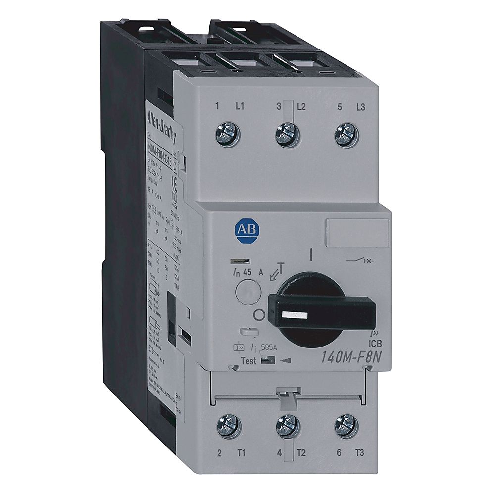
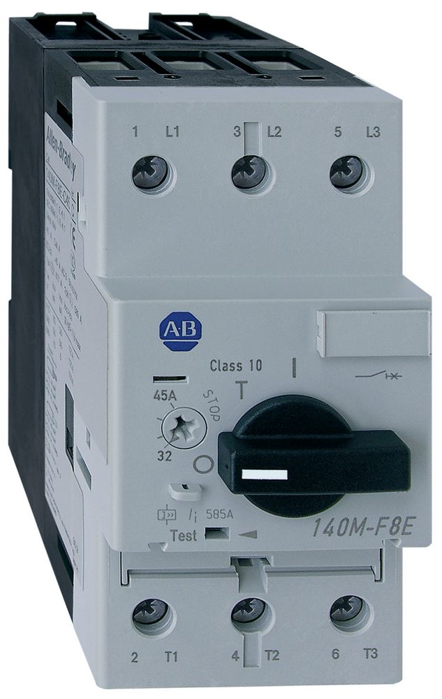
140M-F8N-C32-BX
Motor Circuit Protector Circuit- Breaker
Rockwell Automation announces that as of March 31, 2025, the Motor Circuit Protector Circuit- Breaker will be discontinued and no longer available for sale. Customers are encouraged to remove references to the affected product(s)
Discontinued Date:
March 31, 2025
Replacement Category:
Engineering Replacement
| Number of auxiliary contacts as normally open contact |
1
|
|---|---|
| Number of poles |
3
|
| With integrated under voltage release |
False
|
| Complete device with protection unit |
True
|
| Rated permanent current Iu |
32 A
|
| Rated voltage |
230 V
|
| Type of control element |
Turn button
|
| Rated frequency |
60 Hz
|
| Rated short-circuit breaking capacity lcu at 400 V, 50/60 Hz |
65 kA
|
| Current range |
32 A
|
| Rated operational current (Ie) |
32 A
|
| Magnetic release current |
416 A
|
| Magnetic trip current |
416 A
|
| Hp rating, max |
7.5Hp @ 200V, 3-phase
|
| Back up fuse (gG, gL) current rating (if Icc ≥ Icu ) |
125A @ 500V
|
| Ultimate short circuit breaking capacity (Icu) |
65kA @ 440/460V
|
| Rated insulation voltage (Ui) |
690V per IEC, SEV, VDE0660
|
| KW rating, max |
AC-3: 7.5 kW @ 230V, 3-phase
|
| Switching of standard motors |
AC-3: 7.5 kW @ 230/240V
|
| Total power loss (Pv) for circuit breaker |
9 to 16 W @ rated load operating temperature
|
| Electrical life cycle |
30000 ops (Ie maximum)
|
| Rated thermal current (Ith) |
6.3 to 45 A @ up to 60°C ambient temperature
|
| Fuse or circuit breaker, max |
UL 508-manual motor controller: 600 A
|
| Rated impulse withstand voltage (Uimp) |
Main circuits/overvoltage category: 6 kV/III
|
| Short circuit current for group motor installation, max |
UL 508-manual motor controller: 65kA @ 480V
|
| Short circuit current for motor disconnect, max |
UL 508-manual motor controller: 65kA @ 480V
|
| Rated service short-circuit breaking capacity (Ics) |
6kA @ 690V
|
| Short circuit current, max |
UL-508-Type E self-protected combination motor controller with 100-C contactor: 65 kA @ 480Y/277V
|
| Protection type |
Fixed magnetic only (13 x In)
|
| Motor drive integrated |
False
|
| With switched-off indicator |
False
|
| Motor drive optional |
True
|
| Position of connection for main current circuit |
Front side
|
| Type of electrical connection of main circuit |
Screw connection
|
| Switching frequency, max |
25 ops/h
|
| Rated short-circuit breaking capacity lcu at 480 V, 50/60 Hz |
65 kA @ Group motor
|
| Phase loss protection |
Differential release
|
| Protection class |
IP2X from front with front (upper) terminal wired
|
| Suitable for DIN rail (top hat rail) mounting |
True
|
|---|---|
| DIN rail (top hat rail) mounting optional |
True
|
| Degree of protection (IP) |
IP2X
|
| Weight |
782 lb
|
| Mechanical life operations |
30000 /h
|
| Breaking capacity |
High breaking capacity
|
| Vibration |
Ops (60068-2-6): 5 g
|
| Shock |
Transport (60068-2-27): 30 g, 11 ms, all axes
|
| Factory option |
Circuit-breaker auxiliary contact, front mount 1 NO
|
| Ambient temperature compensation |
-20 °C
|
|---|---|
| Operating temperature |
-25 °F
|
| Storage temperature |
-40 °F
|
| Dependence on temperature |
No current reduction @ 60 °C
|
| Pollution degree |
3
|
| Altitude |
2000 m (NN)
|
| Moisture heat |
40 °C, relative humidity 93 %, 56 d
|
| Dry heat |
100 °C, relative humidity < 50 %, 7 d
|
| Moisture change climate |
23 °C/83 % relative humidity and 40 °C/92 % relative humidity, 56 cycles
|
| Frame size |
Frame size F, 45 A
|
|---|---|
| Contactor size, min |
UL-508-Type E self-protected combination motor controller with 100-C contactor: 100-C30
|
| Device construction |
Built-in device fixed built-in technique
|
| Utilization category |
Motor starter: AC-3 (IEC60947-4-1)
|
|---|
| Drawings | |
|---|---|
| 3D Drawing (STP) | Download (ZIP) |
| Product Drawing | Drawing (DWG) |
| Drawings |
|---|
| 3D Drawing (STP) Download (ZIP) |
| Product Drawing Drawing (DWG) |
Sign in to your Rockwell Automation account to view and download technical drawings.
Sign In
| General | Publication |
|---|---|
| Short Circuit Ratings Data Sheet | -- |
| Product Cutsheet | -- |
| Technical Data | Publication |
|---|---|
| 140m-td002_-en-p | 140M-TD002 |
Looking for more documentation?
Find curated technical documentation for this product in the Technical Documentation Center, or search our full Literature Library.
Search the Literature Library
- China CCC
This product was certified with the above certifications as of {}. Products sold before or after this date might carry different certifications. Please review the product label to check for the certifications your specific product carries.
| Technotes |
|---|
Looking for more Technotes?
Find questions and answers from Rockwell Automation technical experts for this product in our Knowledgebase.
Search Knowledgebase
Technical Specifications
| Number of auxiliary contacts as normally open contact |
1
|
|---|---|
| Number of poles |
3
|
| With integrated under voltage release |
False
|
| Complete device with protection unit |
True
|
| Rated permanent current Iu |
32 A
|
| Rated voltage |
230 V
|
| Type of control element |
Turn button
|
| Rated frequency |
60 Hz
|
| Rated short-circuit breaking capacity lcu at 400 V, 50/60 Hz |
65 kA
|
| Current range |
32 A
|
| Rated operational current (Ie) |
32 A
|
| Magnetic release current |
416 A
|
| Magnetic trip current |
416 A
|
| Hp rating, max |
7.5Hp @ 200V, 3-phase
|
| Back up fuse (gG, gL) current rating (if Icc ≥ Icu ) |
125A @ 500V
|
| Ultimate short circuit breaking capacity (Icu) |
65kA @ 440/460V
|
| Rated insulation voltage (Ui) |
690V per IEC, SEV, VDE0660
|
| KW rating, max |
AC-3: 7.5 kW @ 230V, 3-phase
|
| Switching of standard motors |
AC-3: 7.5 kW @ 230/240V
|
| Total power loss (Pv) for circuit breaker |
9 to 16 W @ rated load operating temperature
|
| Electrical life cycle |
30000 ops (Ie maximum)
|
| Rated thermal current (Ith) |
6.3 to 45 A @ up to 60°C ambient temperature
|
| Fuse or circuit breaker, max |
UL 508-manual motor controller: 600 A
|
| Rated impulse withstand voltage (Uimp) |
Main circuits/overvoltage category: 6 kV/III
|
| Short circuit current for group motor installation, max |
UL 508-manual motor controller: 65kA @ 480V
|
| Short circuit current for motor disconnect, max |
UL 508-manual motor controller: 65kA @ 480V
|
| Rated service short-circuit breaking capacity (Ics) |
6kA @ 690V
|
| Short circuit current, max |
UL-508-Type E self-protected combination motor controller with 100-C contactor: 65 kA @ 480Y/277V
|
| Protection type |
Fixed magnetic only (13 x In)
|
| Motor drive integrated |
False
|
| With switched-off indicator |
False
|
| Motor drive optional |
True
|
| Position of connection for main current circuit |
Front side
|
| Type of electrical connection of main circuit |
Screw connection
|
| Switching frequency, max |
25 ops/h
|
| Rated short-circuit breaking capacity lcu at 480 V, 50/60 Hz |
65 kA @ Group motor
|
| Phase loss protection |
Differential release
|
| Protection class |
IP2X from front with front (upper) terminal wired
|
| Suitable for DIN rail (top hat rail) mounting |
True
|
|---|---|
| DIN rail (top hat rail) mounting optional |
True
|
| Degree of protection (IP) |
IP2X
|
| Weight |
782 lb
|
| Mechanical life operations |
30000 /h
|
| Breaking capacity |
High breaking capacity
|
| Vibration |
Ops (60068-2-6): 5 g
|
| Shock |
Transport (60068-2-27): 30 g, 11 ms, all axes
|
| Factory option |
Circuit-breaker auxiliary contact, front mount 1 NO
|
| Ambient temperature compensation |
-20 °C
|
|---|---|
| Operating temperature |
-25 °F
|
| Storage temperature |
-40 °F
|
| Dependence on temperature |
No current reduction @ 60 °C
|
| Pollution degree |
3
|
| Altitude |
2000 m (NN)
|
| Moisture heat |
40 °C, relative humidity 93 %, 56 d
|
| Dry heat |
100 °C, relative humidity < 50 %, 7 d
|
| Moisture change climate |
23 °C/83 % relative humidity and 40 °C/92 % relative humidity, 56 cycles
|
| Frame size |
Frame size F, 45 A
|
|---|---|
| Contactor size, min |
UL-508-Type E self-protected combination motor controller with 100-C contactor: 100-C30
|
| Device construction |
Built-in device fixed built-in technique
|
| Utilization category |
Motor starter: AC-3 (IEC60947-4-1)
|
|---|
Drawings
| Drawings | |
|---|---|
| 3D Drawing (STP) | Download (ZIP) |
| Product Drawing | Drawing (DWG) |
| Drawings |
|---|
| 3D Drawing (STP) Download (ZIP) |
| Product Drawing Drawing (DWG) |
Sign in to your Rockwell Automation account to view and download technical drawings.
Sign In
Documents
|
Short Circuit Ratings Data Sheet
General
-- |
|
Product Cutsheet
General
-- |
|
140m-td002_-en-p
Technical Data
140M-TD002 |
| General | Publication |
|---|---|
| Short Circuit Ratings Data Sheet | -- |
| Product Cutsheet | -- |
| Technical Data | Publication |
| 140m-td002_-en-p | 140M-TD002 |
Looking for more documentation?
Find curated technical documentation for this product in the Technical Documentation Center, or search our full Literature Library.
Search the Literature Library
Certifications
- China CCC
This product was certified with the above certifications as of {}. Products sold before or after this date might carry different certifications. Please review the product label to check for the certifications your specific product carries.
Accessories
Alternative Products
Technotes
| Technotes |
|---|
Looking for more Technotes?
Find questions and answers from Rockwell Automation technical experts for this product in our Knowledgebase.
Search Knowledgebase
Copyright ©2026 Rockwell Automation, Inc.