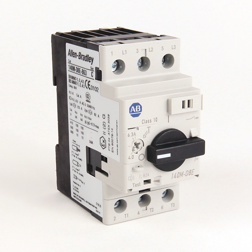
Loading
Allen-Bradley 140M-D8E-B63 product image
Allen Bradley
140M-D8E-B63

Motor Protection Circuit-Breaker

PrintPrint
Print
EmailEmail
Share
Product RegistrationProduct Registration
QR code
Allen-Bradley 140M-D8E-B63 product image
Allen Bradley
Lifecycle status: Discontinued
ErrorsErrors
Rockwell Automation announces that as of February 25, 2022, the Motor Protection Circuit-Breaker will be discontinued and no longer available for sale. Customers are encouraged to remove references to the affected product(s)
Discontinued Date: February 25, 2022 Replacement Category: Engineering Replacement Replacement Product: 140MT-D9E-B63 [https://www.rockwellautomation.com/en-us/products/details.140MT-D9E-B63.html]
Product at a glance
Replacement Available
Add to BoM
  • Get Support
Technical Specifications
Drawings
Documents
Certifications
Technotes
With integrated auxiliary switch False
With integrated under voltage release False
Rated short-circuit breaking capacity lcu at 400 V, AC 100 kA
Rated operation power at AC-3, 400 V 2.2 kw
Rated permanent current Iu 6.3 A
Rated operation power at AC-3, 230 V 1.5 kw
Rated operating voltage 230 A
Type of control element Turn button
Overload release current setting 4 A
Type of electrical connection of main circuit Screw connection
Rated frequency 60 Hz
Magnetic release current per IEC 82 A
Rated operational current (Ie) per IEC 6.3 A
Magnetic trip current 82 A
Rated supply current (Ie) 1.6 A
Total power loss (Pv) for circuit breaker at rated load operating temperature 6 W
Current range 4 to 6.3 A
Ultimate short circuit breaking capacity (Icu) per IEC 6kA @ 690V
Rated service short circuit breaking capacity (Ics) per IEC 6kA @ 690V
Hp rating, max 5Hp @ 575V, 3-phase
Rated insulation voltage (Ui) 690V per IEC, SEV, VDE0660
Electrical life cycle 100000 ops (Ie maximum)
Switching of standard motors per IEC 4.0 kW @ 690V (AC-3), 3-phase
KW rating, max 4 kW @ 690V (AC-3), 3-phase
Back up fuse (gG, gL) current rating (if Icc ≥ Icu ) per IEC No back-up fuse required @ 500V
Short circuit current (Type 2 coordination), max 65kA @ 480V
Short circuit current for group motor installation with 100-C contactor, max 65kA @ 480V, UL 508-manual motor controller
Short circuit current for motor disconnect with 100-C contactor, max 65kA @ 480V, UL 508-manual motor controller
Short circuit current for group motor installation with 100-K contactor, max 65kA @ 480V, UL 508-manual motor controller
Short circuit current for motor disconnect with 100-K contactor, max 65kA @ 480V, UL 508-manual motor controller
Rated thermal current (Ith) 1.6...32 A @ up to 60 °C ambient temperature
Short circuit current for combination motor controller with 100-C contactor, max 65 kA @ 480Y/277V per UL 508-self-protected (Type E)
Short circuit current for tap conductor protection, max 65 kA @ 480Y/277V per UL 508-manual motor controller
Short circuit current for combination motor controller, max 65 kA @ 480Y/277V, UL 508-Type F
Fuse or circuit breaker per NEC, max 450 A, UL 508-manual motor controller with 100-C contactor
Rated impulse withstand voltage (Uimp) Main circuits/overvoltage category: 6 kV/III
Short circuit current for group motor installation, max 65kA @ 480V, UL 508-manual motor controller
Short circuit current for motor disconnect, max 65kA @ 480V, UL 508-manual motor controller
Number of poles 3
With thermal protection True
Phase failure sensitive True
Switch off technique Thermomagnetic
Switching frequency, max 25 ops/h
Overload trip class 10
Phase loss protection Differential release
Fuse or circuit breaker rating with 100-K contactor per NEC, max 450 A, UL 508-manual motor controller
Degree of protection (IP) IP2X
Weight 373 lb
Mechanical life operations 100000 /h
Breaking capacity High breaking capacity
Protection type Adjustable thermal/fixed magnetic (13 x In)
Factory option No circuit-breaker auxiliary or trip contacts
Vibration resistance Ops (60068-2-6): 5 G
Shock resistance Transport (60068-2-27): 30 g, 11 ms, all axes
Ambient storage temperature -40 °C
Ambient operating temperature -25 °C
Ambient temperature compensation -20 °C
Site altitude 2000 m (NN)
Dependence on temperature No current reduction
Magnetic release current (±20 %) Fixed setting 13...14 x Ie max. Ie max. = maximum values of setting ranges
Pollution degree 3
Moisture heat (60068-2-3) 40 °C, relative humidity 93 %, 56 d
Dry heat (60086-2-2) 100 °C, relative humidity < 50 %, 7 d
Moisture change climate (600068-2-30) 23 °C/83 % relative humidity and 40 °C/92 % relative humidity, 56 cycles
Frame size Frame size D, 32 A
Contactor size for combination motor controller, min 100-K05, UL-508-Type F
Contactor size, min 100-K05, UL 508-manual motor controller
Device construction Built-in device fixed built-in technique
Utilization category Motor starter: AC-3 (IEC60947-4-1)
Overload protection characteristics IEC 60947-4-1 motor protection
Sign in to your Rockwell Automation account to view and download technical drawings.
Sign In
Type Resource Publication
Technical Data 140m-td002_-en-p 140M-TD002
Looking for more documentation?
Find curated technical documentation for this product in the Technical Documentation Center, or search our full Literature Library.
Search the Literature Library Chevron RightChevron Right
China CCC
  • China CCC

This product was certified with the above certifications as of 2025-08-26. Products sold before or after this date might carry different certifications. Please review the product label to check for the certifications your specific product carries.

Looking for more Technotes?
Find questions and answers from Rockwell Automation technical experts for this product in our Knowledgebase.
Search Knowledgebase Chevron RightChevron Right
Technical Specifications
With integrated auxiliary switch False
With integrated under voltage release False
Rated short-circuit breaking capacity lcu at 400 V, AC 100 kA
Rated operation power at AC-3, 400 V 2.2 kw
Rated permanent current Iu 6.3 A
Rated operation power at AC-3, 230 V 1.5 kw
Rated operating voltage 230 A
Type of control element Turn button
Overload release current setting 4 A
Type of electrical connection of main circuit Screw connection
Rated frequency 60 Hz
Magnetic release current per IEC 82 A
Rated operational current (Ie) per IEC 6.3 A
Magnetic trip current 82 A
Rated supply current (Ie) 1.6 A
Total power loss (Pv) for circuit breaker at rated load operating temperature 6 W
Current range 4 to 6.3 A
Ultimate short circuit breaking capacity (Icu) per IEC 6kA @ 690V
Rated service short circuit breaking capacity (Ics) per IEC 6kA @ 690V
Hp rating, max 5Hp @ 575V, 3-phase
Rated insulation voltage (Ui) 690V per IEC, SEV, VDE0660
Electrical life cycle 100000 ops (Ie maximum)
Switching of standard motors per IEC 4.0 kW @ 690V (AC-3), 3-phase
KW rating, max 4 kW @ 690V (AC-3), 3-phase
Back up fuse (gG, gL) current rating (if Icc ≥ Icu ) per IEC No back-up fuse required @ 500V
Short circuit current (Type 2 coordination), max 65kA @ 480V
Short circuit current for group motor installation with 100-C contactor, max 65kA @ 480V, UL 508-manual motor controller
Short circuit current for motor disconnect with 100-C contactor, max 65kA @ 480V, UL 508-manual motor controller
Short circuit current for group motor installation with 100-K contactor, max 65kA @ 480V, UL 508-manual motor controller
Short circuit current for motor disconnect with 100-K contactor, max 65kA @ 480V, UL 508-manual motor controller
Rated thermal current (Ith) 1.6...32 A @ up to 60 °C ambient temperature
Short circuit current for combination motor controller with 100-C contactor, max 65 kA @ 480Y/277V per UL 508-self-protected (Type E)
Short circuit current for tap conductor protection, max 65 kA @ 480Y/277V per UL 508-manual motor controller
Short circuit current for combination motor controller, max 65 kA @ 480Y/277V, UL 508-Type F
Fuse or circuit breaker per NEC, max 450 A, UL 508-manual motor controller with 100-C contactor
Rated impulse withstand voltage (Uimp) Main circuits/overvoltage category: 6 kV/III
Short circuit current for group motor installation, max 65kA @ 480V, UL 508-manual motor controller
Short circuit current for motor disconnect, max 65kA @ 480V, UL 508-manual motor controller
Number of poles 3
With thermal protection True
Phase failure sensitive True
Switch off technique Thermomagnetic
Switching frequency, max 25 ops/h
Overload trip class 10
Phase loss protection Differential release
Fuse or circuit breaker rating with 100-K contactor per NEC, max 450 A, UL 508-manual motor controller
Degree of protection (IP) IP2X
Weight 373 lb
Mechanical life operations 100000 /h
Breaking capacity High breaking capacity
Protection type Adjustable thermal/fixed magnetic (13 x In)
Factory option No circuit-breaker auxiliary or trip contacts
Vibration resistance Ops (60068-2-6): 5 G
Shock resistance Transport (60068-2-27): 30 g, 11 ms, all axes
Ambient storage temperature -40 °C
Ambient operating temperature -25 °C
Ambient temperature compensation -20 °C
Site altitude 2000 m (NN)
Dependence on temperature No current reduction
Magnetic release current (±20 %) Fixed setting 13...14 x Ie max. Ie max. = maximum values of setting ranges
Pollution degree 3
Moisture heat (60068-2-3) 40 °C, relative humidity 93 %, 56 d
Dry heat (60086-2-2) 100 °C, relative humidity < 50 %, 7 d
Moisture change climate (600068-2-30) 23 °C/83 % relative humidity and 40 °C/92 % relative humidity, 56 cycles
Frame size Frame size D, 32 A
Contactor size for combination motor controller, min 100-K05, UL-508-Type F
Contactor size, min 100-K05, UL 508-manual motor controller
Device construction Built-in device fixed built-in technique
Utilization category Motor starter: AC-3 (IEC60947-4-1)
Overload protection characteristics IEC 60947-4-1 motor protection
Drawings
Sign in to your Rockwell Automation account to view and download technical drawings.
Sign In
Documents
140m-td002_-en-p Technical Data
140M-TD002
Type Resource Publication
Technical Data 140m-td002_-en-p 140M-TD002
Looking for more documentation?
Find curated technical documentation for this product in the Technical Documentation Center, or search our full Literature Library.
Search the Literature Library Chevron RightChevron Right
Certifications
China CCC
  • China CCC

This product was certified with the above certifications as of 2025-08-26. Products sold before or after this date might carry different certifications. Please review the product label to check for the certifications your specific product carries.

Technotes
Looking for more Technotes?
Find questions and answers from Rockwell Automation technical experts for this product in our Knowledgebase.
Search Knowledgebase Chevron RightChevron Right
Loading
Find your nearest distributor
Change location
EmailEmail
PhonePhone
Find a partner Chevron RightChevron Right
Motor Protection Circuit-Breaker
CloseClose
140M-D8E-B63
Close
Print
Allen-Bradley 140M-D8E-B63 product image
Phone:
Call
Rockwell Automation Home
Copyright ©2025 Rockwell Automation, Inc.
Sign in to your Rockwell Automation account to submit a repair documentation request.
Sign In
Request repair documentation
All fields with * are required for processing your request.
This field is required
Documentation of liability insurance is required for anyone who is requesting documentation for product repairs.
UploadUpload
Please upload documentation of liability insurance.*
1 file selected
CloseClose
File size is too large. Must be less than 5 MB.
Accepted file types: zip, pdf; Maximum size: 5 MB.
Right to Repair Terms and Conditions
Rockwell Automation is making, parts, and service documentation available at your request in compliance with applicable right to repair laws and regulations. By signing below, you are agreeing to the following terms and conditions of your purchase of Rockwell Automation genuine repair parts for repair of a Rockwell Automation product. As used below, “Self Service Repair Parts” means genuine Rockwell Automation parts (components of Rockwell Automation products) purchased from Rockwell Automation for installation in a Rockwell Automation product as part of a Self Service Repair. Self Service Repair Parts may be new or previously used genuine Rockwell Automation parts that have been tested and passed Rockwell Automation functional requirements. “Self Service Repair Tools” means equipment and related materials purchased for the purpose of performing repairs.
Your request has been successfully submitted.
Please allow up to 5 business days to receive a response to your inquiry.
  1. Chevron LeftChevron Left Rockwell Automation Home Chevron RightChevron Right
  2. Chevron LeftChevron Left Products Chevron RightChevron Right
Please update your cookie preferences to continue.
This feature requires cookies to enhance your experience. Please update your preferences to allow for these cookies:
  • Social Media Cookies
  • Functional Cookies
  • Performance Cookies
  • Marketing Cookies
  • All Cookies
You can update your preferences at any time. For more information please see our {0} Privacy Policy
CloseClose