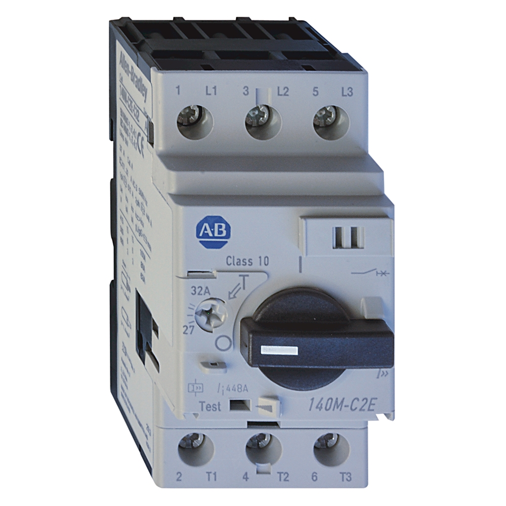
Motor Protection Circuit- Breaker
| Unique Product Identifier |
140m-c2e-c16-kn
|
|---|---|
| UPC |
781180052811
|
| Estimated Lead Time |
31 days
|
| Standard Warranty Duration |
1 year See details |
| Country of Origin |
Switzerland
|
| EU Importer Address |
Rockwell Automation N.V |
| EU Authorized Representative Address |
Rockwell Automation N.V |
The information provided by Rockwell Automation on www.rockwellautomation.com (the “Site”) is for demonstration purposes only and may be incomplete or inaccurate. All information is provided “as is”, and Rockwell Automation makes no representations or warranties of any kind, express or implied, regarding the accuracy, adequacy, validity, reliability, or completeness of any information on the Site. Use of this information is at your own risk.
| Amperage Rating |
10 - 16A,MxRtg MCPs(no OvPrt)is 1200.0A
|
|---|
| With integrated auxiliary switch |
False
|
|---|---|
| With integrated under voltage release |
False
|
| Rated short-circuit breaking capacity lcu at 400 V, AC |
65 kA
|
| Rated operation power at AC-3, 400 V |
7.5 kw
|
| Rated permanent current Iu |
16 A
|
| Rated operation power at AC-3, 230 V |
4 kw
|
| Rated operating voltage |
230 A
|
| Type of control element |
Turn button
|
| Overload release current setting |
10 A
|
| Type of electrical connection of main circuit |
Screw connection
|
| Magnetic release current per IEC |
208 A
|
| Rated operational current (Ie) per IEC |
16 A
|
| Magnetic trip current |
208 A
|
| Rated supply current (Ie) |
0.1 A
|
| Short circuit current (Icu) for group motor installation, max |
30kA @ 480V
|
| Current range |
10...16 A
|
| Ultimate short circuit breaking capacity (Icu) per IEC |
65kA @ 400/415V
|
| Rated service short circuit breaking capacity (Ics) per IEC |
6kA @ 500V
|
| Hp rating, max |
5Hp @ 230V, 3-phase
|
| Rated insulation voltage (Ui) |
690V per IEC, SEV, VDE0660
|
| Electrical life cycle |
100000 ops (Ie maximum)
|
| Short circuit current for self-protected combination motor controller with 100-C contactor, max |
30 kA @ 480Y/277V, UL 508-Type E
|
| Short circuit current for combination motor controller with 100-K contactor, max |
30 kA @ 480Y/277V, UL 508-Type F
|
| Switching of standard motors per IEC |
7.5 kW @ 400/415V (AC-3), 3-phase
|
| KW rating, max |
7.5 kW @ 415V (AC-3), 3-phase
|
| Back up fuse (gG, gL) current rating (if Icc ≥ Icu ) per IEC |
No back-up fuse required @ 230/240V
|
| Short circuit current (Type 2 coordination), max |
50kA @ 400V
|
| Short circuit current for group motor installation with 100-C contactor, max |
30kA @ 600V, UL 508-manual motor controller
|
| Short circuit current for motor disconnect with 100-C contactor, max |
30kA @ 480V, UL 508-manual motor controller
|
| Short circuit current for group motor installation with 100-K contactor, max |
30kA @ 600V, UL 508-manual motor controller
|
| Short circuit current for motor disconnect with 100-K contactor, max |
30kA @ 600V, UL 508-manual motor controller
|
| Total power loss (Pv) for circuit breaker |
6...11.5 W @ rated load operating temperature
|
| Rated thermal current (Ith) |
0.1...32A @ 60°C ambient temperature
|
| Short circuit current for combination motor controller with 100-C contactor, max |
30 kA @ 480Y/277V, UL 508-Type F
|
| Short circuit current for tap conductor protection, max |
30 kA @ 480Y/277V, UL 508-manual motor controller
|
| Short circuit current for combination motor controller, max |
30kA @ 480V/277V, UL 508-self-protected (Type E)
|
| Fuse or circuit breaker per NEC, max |
450 A, UL 508-manual motor controller
|
| Rated impulse withstand voltage (Uimp) |
Main circuits/overvoltage category: 6 kV/III
|
| Short circuit current for group motor installation, max |
30kA @ 600V per UL 508-manual motor controller
|
| Short circuit current for motor disconnect, max |
30kA @ 600V, UL 508-manual motor controller
|
| Number of poles |
3
|
| With thermal protection |
True
|
| Phase failure sensitive |
True
|
| Switch off technique |
Thermomagnetic
|
| Switching frequency, max |
25 ops/h
|
| Trip class |
10
|
| Rated frequency |
50/60 Hz
|
| Phase loss protection |
Differential release
|
| Fuse or circuit breaker rating with 100-K contactor per NEC, max |
450 A, UL 508-manual motor controller
|
| Fuse or circuit breaker rating with 100-C contactor per NEC, max |
450 A, UL 508-manual motor controller
|
| Width |
45 mm
|
|---|---|
| Depth |
70 mm
|
| Height |
90 mm
|
| Packaging |
Single pack
|
| Frame size |
Frame size C, 32 A
|
| Contactor size (Type 2 coordination), min |
100-C30 @ 600V
|
| Contactor size (100-K), min |
100-K12: UL-508-Type F combination motor controller
|
| Contactor size (100-C), min |
100-C12, UL-508-Type F combination motor controller
|
| Device construction |
Built-in device fixed built-in technique
|
| Degree of protection (IP) |
IP2X
|
|---|---|
| Weight |
317 lb
|
| Mechanical life operations |
100000 /h
|
| Breaking capacity |
Standard breaking capacity
|
| Shock |
Transport (60068-2-27): 30 G, 11 ms, all axes
|
| Protection type |
Adjustable thermal/fixed magnetic (13 x In)
|
| Factory option |
No circuit-breaker auxiliary or trip contacts
|
| Vibration |
Ops (60068-2-6): 5 G
|
| Ambient storage temperature |
-40 °C
|
|---|---|
| Ambient operating temperature |
-25 °C
|
| Ambient temperature compensation |
-20 °C
|
| Site altitude |
2000 m (NN)
|
| Moisture heat |
40 °C, relative humidity 93 %, 56 d, (60068-2-3)
|
| Dry heat |
100 °C, relative humidity < 50 %, 7 d, (60086-2-2)
|
| Dependence on temperature |
No current reduction @ 60 °C
|
| Moisture change climate |
23 °C/83 % relative humidity and 40 °C/92 % relative humidity, 56 cycles, (600068-2-30)
|
| Magnetic release current (±20 %) |
Fixed setting 13...14 x Ie max. Ie max. = maximum values of setting ranges
|
| Pollution degree |
3
|
| Technical Data | Publication |
|---|---|
| 140m-td002_-en-p | 140M-TD002 |
- MOROCCO DOC
This product was certified with the above certifications as of {}. Products sold before or after this date might carry different certifications. Please review the product label to check for the certifications your specific product carries.
| Technotes |
|---|
Overview
| Unique Product Identifier |
140m-c2e-c16-kn
|
|---|---|
| UPC |
781180052811
|
| Estimated Lead Time |
31 days
|
| Standard Warranty Duration |
1 year See details |
| Country of Origin |
Switzerland
|
| EU Importer Address |
Rockwell Automation N.V |
| EU Authorized Representative Address |
Rockwell Automation N.V |
The information provided by Rockwell Automation on www.rockwellautomation.com (the “Site”) is for demonstration purposes only and may be incomplete or inaccurate. All information is provided “as is”, and Rockwell Automation makes no representations or warranties of any kind, express or implied, regarding the accuracy, adequacy, validity, reliability, or completeness of any information on the Site. Use of this information is at your own risk.
Technical Specifications
| Amperage Rating |
10 - 16A,MxRtg MCPs(no OvPrt)is 1200.0A
|
|---|
| With integrated auxiliary switch |
False
|
|---|---|
| With integrated under voltage release |
False
|
| Rated short-circuit breaking capacity lcu at 400 V, AC |
65 kA
|
| Rated operation power at AC-3, 400 V |
7.5 kw
|
| Rated permanent current Iu |
16 A
|
| Rated operation power at AC-3, 230 V |
4 kw
|
| Rated operating voltage |
230 A
|
| Type of control element |
Turn button
|
| Overload release current setting |
10 A
|
| Type of electrical connection of main circuit |
Screw connection
|
| Magnetic release current per IEC |
208 A
|
| Rated operational current (Ie) per IEC |
16 A
|
| Magnetic trip current |
208 A
|
| Rated supply current (Ie) |
0.1 A
|
| Short circuit current (Icu) for group motor installation, max |
30kA @ 480V
|
| Current range |
10...16 A
|
| Ultimate short circuit breaking capacity (Icu) per IEC |
65kA @ 400/415V
|
| Rated service short circuit breaking capacity (Ics) per IEC |
6kA @ 500V
|
| Hp rating, max |
5Hp @ 230V, 3-phase
|
| Rated insulation voltage (Ui) |
690V per IEC, SEV, VDE0660
|
| Electrical life cycle |
100000 ops (Ie maximum)
|
| Short circuit current for self-protected combination motor controller with 100-C contactor, max |
30 kA @ 480Y/277V, UL 508-Type E
|
| Short circuit current for combination motor controller with 100-K contactor, max |
30 kA @ 480Y/277V, UL 508-Type F
|
| Switching of standard motors per IEC |
7.5 kW @ 400/415V (AC-3), 3-phase
|
| KW rating, max |
7.5 kW @ 415V (AC-3), 3-phase
|
| Back up fuse (gG, gL) current rating (if Icc ≥ Icu ) per IEC |
No back-up fuse required @ 230/240V
|
| Short circuit current (Type 2 coordination), max |
50kA @ 400V
|
| Short circuit current for group motor installation with 100-C contactor, max |
30kA @ 600V, UL 508-manual motor controller
|
| Short circuit current for motor disconnect with 100-C contactor, max |
30kA @ 480V, UL 508-manual motor controller
|
| Short circuit current for group motor installation with 100-K contactor, max |
30kA @ 600V, UL 508-manual motor controller
|
| Short circuit current for motor disconnect with 100-K contactor, max |
30kA @ 600V, UL 508-manual motor controller
|
| Total power loss (Pv) for circuit breaker |
6...11.5 W @ rated load operating temperature
|
| Rated thermal current (Ith) |
0.1...32A @ 60°C ambient temperature
|
| Short circuit current for combination motor controller with 100-C contactor, max |
30 kA @ 480Y/277V, UL 508-Type F
|
| Short circuit current for tap conductor protection, max |
30 kA @ 480Y/277V, UL 508-manual motor controller
|
| Short circuit current for combination motor controller, max |
30kA @ 480V/277V, UL 508-self-protected (Type E)
|
| Fuse or circuit breaker per NEC, max |
450 A, UL 508-manual motor controller
|
| Rated impulse withstand voltage (Uimp) |
Main circuits/overvoltage category: 6 kV/III
|
| Short circuit current for group motor installation, max |
30kA @ 600V per UL 508-manual motor controller
|
| Short circuit current for motor disconnect, max |
30kA @ 600V, UL 508-manual motor controller
|
| Number of poles |
3
|
| With thermal protection |
True
|
| Phase failure sensitive |
True
|
| Switch off technique |
Thermomagnetic
|
| Switching frequency, max |
25 ops/h
|
| Trip class |
10
|
| Rated frequency |
50/60 Hz
|
| Phase loss protection |
Differential release
|
| Fuse or circuit breaker rating with 100-K contactor per NEC, max |
450 A, UL 508-manual motor controller
|
| Fuse or circuit breaker rating with 100-C contactor per NEC, max |
450 A, UL 508-manual motor controller
|
| Width |
45 mm
|
|---|---|
| Depth |
70 mm
|
| Height |
90 mm
|
| Packaging |
Single pack
|
| Frame size |
Frame size C, 32 A
|
| Contactor size (Type 2 coordination), min |
100-C30 @ 600V
|
| Contactor size (100-K), min |
100-K12: UL-508-Type F combination motor controller
|
| Contactor size (100-C), min |
100-C12, UL-508-Type F combination motor controller
|
| Device construction |
Built-in device fixed built-in technique
|
| Degree of protection (IP) |
IP2X
|
|---|---|
| Weight |
317 lb
|
| Mechanical life operations |
100000 /h
|
| Breaking capacity |
Standard breaking capacity
|
| Shock |
Transport (60068-2-27): 30 G, 11 ms, all axes
|
| Protection type |
Adjustable thermal/fixed magnetic (13 x In)
|
| Factory option |
No circuit-breaker auxiliary or trip contacts
|
| Vibration |
Ops (60068-2-6): 5 G
|
| Ambient storage temperature |
-40 °C
|
|---|---|
| Ambient operating temperature |
-25 °C
|
| Ambient temperature compensation |
-20 °C
|
| Site altitude |
2000 m (NN)
|
| Moisture heat |
40 °C, relative humidity 93 %, 56 d, (60068-2-3)
|
| Dry heat |
100 °C, relative humidity < 50 %, 7 d, (60086-2-2)
|
| Dependence on temperature |
No current reduction @ 60 °C
|
| Moisture change climate |
23 °C/83 % relative humidity and 40 °C/92 % relative humidity, 56 cycles, (600068-2-30)
|
| Magnetic release current (±20 %) |
Fixed setting 13...14 x Ie max. Ie max. = maximum values of setting ranges
|
| Pollution degree |
3
|
Drawings
Documents
|
140m-td002_-en-p
Technical Data
140M-TD002 |
| Technical Data | Publication |
|---|---|
| 140m-td002_-en-p | 140M-TD002 |
Certifications
- MOROCCO DOC
This product was certified with the above certifications as of {}. Products sold before or after this date might carry different certifications. Please review the product label to check for the certifications your specific product carries.
Alternative Products
Technotes
| Technotes |
|---|