| Number of poles |
3
|
|---|---|
| With integrated under voltage release |
False
|
| Integrated earth fault protection |
False
|
| Complete device with protection unit |
True
|
| Rated permanent current Iu |
1200 A
|
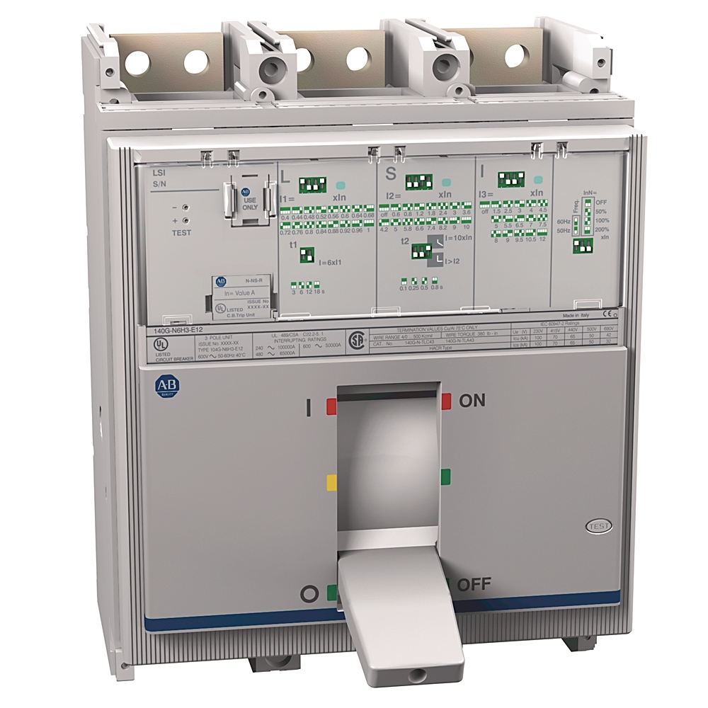
| Type of control element |
Toggle
|
| Rated impulse withstand voltage (Uimp) |
8 kV
|
| Frame size |
1200 A
|
| Current range |
80% MCCB
|
| Voltage for reverse-fed circuit breaker, max |
690V AC per IEC
|
| Watt loss |
Electronic type: 252 W
|
| Insulation voltage (Ui) |
Rated 1000V per IEC
|
| Protection type—Electronic I (lnstantaneous trip units, 80 % continuous rated) |
I3 = 1.5...12 x In (OFF, 1800...14400 A)
|
| Protection type—Electronic I (lnstantaneous trip units, 100 % continuous rated) |
I3 = 1.5...12 x In (OFF, 1800...14400 A)
|
| Electrical life cycle |
60 ops/hr @ 415V AC
|
| Operating current (In), max |
980A @ 70°C (158 ˚F) per IEC (Molded case switch rated current)
|
| Interrupting rating |
65kA @ 240V AC, 50/60 Hz per NEMA, UL, CSA
|
| Rated ultimate short-circuit breaking capacity (Icu) |
IEC 60947-2: 85kA @ 220...230V AC, 50/60 Hz
|
| Rated service short-circuit breaking capacity (Ics) |
IEC 60947-2: 75% Icu (30 kA) @ 525V AC @ 50/60Hz
|
| Protection type—Electronic S (short time trip units, 100 % continuous rated) |
I2 = 0.6...10 x In (OFF, 720...12000 A), t2 = [tsec] @ 10 x In = 0.1, 0.25, 0.5, 0.8 s
|
| Protection type—Electronic L (long time trip units, 80 % continuous rated) |
I1 = 0.4...1 x In (480...1200 A), t1 = [tsec] @ 6 x I1 = 3, 6, 12, 18 s
|
| Protection type—Electronic L (long time trip units, 100 % continuous rated) |
I1 = 0.4...1 x In (480...1200 A), t1 = [tsec] @ 6 x I1 = 3, 6, 12, 18 s
|
| Protection type |
Electronic LSI-long and short time, high instantaneous
|
| Motor drive integrated |
False
|
| With switched-off indicator |
False
|
| Motor drive optional |
True
|
| Position of connection for main current circuit |
Front side
|
| Type of electrical connection of main circuit |
Screw connection
|
| Protection type—Electronic S (short time trip units, 80 % continuous rated) |
I2 = 0.6...10 x In (OFF, 720...12000 A), t2 = [tsec] @ 10 x In = 0.1, 0.25, 0.5, 0.8 s
|
| Suitable for DIN rail (top hat rail) mounting |
False
|
|---|---|
| DIN rail (top hat rail) mounting optional |
False
|
| Degree of protection (IP) |
IP40
|
| Weight |
21.39 lb
|
| Mechanical life operations |
60 /h
|
| Vibration |
2...13.2 Hz ±1 mm, 13.2...100 Hz ±0.7 G
|
| Factory option |
Shunt-trip, 110...127V AC @ 110...125V DC
|
| Height |
268 mm
|
|---|---|
| Device construction |
Built-in device fixed built-in technique
|
| Width |
210 mm
|
|---|---|
| Depth |
154 mm
|
| Storage temperature |
-40 °F
|
| Wire temperature rating |
Al or Cu 75 °C
|
| Operational voltage (Ue) |
90% of voltage rating @ 3000 m (9840 ft) altitude
|
| Rated uninterrupted current (Iu) |
98% of current rating @ 3000 m (9840 ft) altitude
|
| Ambient temperature without derating |
104 °F
|
| Drawings | |
|---|---|
| 3D Model Drawing (PDF) | Download (PDF) |
| 2-Dimensional Drawing (PDF) | Download (PDF) |
| 3-Dimensional STEP model (STP) | Download (ZIP) |
| Product Drawing | Drawing (DWG) |
| Product Drawing | Drawing (DXF) |
| Drawings |
|---|
| 3D Model Drawing (PDF) Download (PDF) |
| 2-Dimensional Drawing (PDF) Download (PDF) |
| 3-Dimensional STEP model (STP) Download (ZIP) |
| Product Drawing Drawing (DWG) |
| Product Drawing Drawing (DXF) |
Sign in to your Rockwell Automation account to view and download technical drawings.
Sign In
| General | Publication |
|---|---|
| Breaker Wars: MCCB vs MPCB vs MCP vs MCB Podcast | -- |
| 140G Specifications and Technical Data | 140G-TD101 |
| Product Cutsheet | -- |
| Link to Literature Library for Installation Instructions | 140G-IN068 |
| Link to Literature Library for Selectivity Guide | 140G-TD050 |
| Technical Data | Publication |
|---|---|
| 140g-td102_-en-p | 140G-TD102 |
Looking for more documentation?
Find curated technical documentation for this product in the Technical Documentation Center, or search our full Literature Library.
Search the Literature Library
- China CCC
This product was certified with the above certifications as of {}. Products sold before or after this date might carry different certifications. Please review the product label to check for the certifications your specific product carries.
Looking for more Technotes?
Find questions and answers from Rockwell Automation technical experts for this product in our Knowledgebase.
Search Knowledgebase
Technical Specifications
| Number of poles |
3
|
|---|---|
| With integrated under voltage release |
False
|
| Integrated earth fault protection |
False
|
| Complete device with protection unit |
True
|
| Rated permanent current Iu |
1200 A
|
| Type of control element |
Toggle
|
| Rated impulse withstand voltage (Uimp) |
8 kV
|
| Frame size |
1200 A
|
| Current range |
80% MCCB
|
| Voltage for reverse-fed circuit breaker, max |
690V AC per IEC
|
| Watt loss |
Electronic type: 252 W
|
| Insulation voltage (Ui) |
Rated 1000V per IEC
|
| Protection type—Electronic I (lnstantaneous trip units, 80 % continuous rated) |
I3 = 1.5...12 x In (OFF, 1800...14400 A)
|
| Protection type—Electronic I (lnstantaneous trip units, 100 % continuous rated) |
I3 = 1.5...12 x In (OFF, 1800...14400 A)
|
| Electrical life cycle |
60 ops/hr @ 415V AC
|
| Operating current (In), max |
980A @ 70°C (158 ˚F) per IEC (Molded case switch rated current)
|
| Interrupting rating |
65kA @ 240V AC, 50/60 Hz per NEMA, UL, CSA
|
| Rated ultimate short-circuit breaking capacity (Icu) |
IEC 60947-2: 85kA @ 220...230V AC, 50/60 Hz
|
| Rated service short-circuit breaking capacity (Ics) |
IEC 60947-2: 75% Icu (30 kA) @ 525V AC @ 50/60Hz
|
| Protection type—Electronic S (short time trip units, 100 % continuous rated) |
I2 = 0.6...10 x In (OFF, 720...12000 A), t2 = [tsec] @ 10 x In = 0.1, 0.25, 0.5, 0.8 s
|
| Protection type—Electronic L (long time trip units, 80 % continuous rated) |
I1 = 0.4...1 x In (480...1200 A), t1 = [tsec] @ 6 x I1 = 3, 6, 12, 18 s
|
| Protection type—Electronic L (long time trip units, 100 % continuous rated) |
I1 = 0.4...1 x In (480...1200 A), t1 = [tsec] @ 6 x I1 = 3, 6, 12, 18 s
|
| Protection type |
Electronic LSI-long and short time, high instantaneous
|
| Motor drive integrated |
False
|
| With switched-off indicator |
False
|
| Motor drive optional |
True
|
| Position of connection for main current circuit |
Front side
|
| Type of electrical connection of main circuit |
Screw connection
|
| Protection type—Electronic S (short time trip units, 80 % continuous rated) |
I2 = 0.6...10 x In (OFF, 720...12000 A), t2 = [tsec] @ 10 x In = 0.1, 0.25, 0.5, 0.8 s
|
| Suitable for DIN rail (top hat rail) mounting |
False
|
|---|---|
| DIN rail (top hat rail) mounting optional |
False
|
| Degree of protection (IP) |
IP40
|
| Weight |
21.39 lb
|
| Mechanical life operations |
60 /h
|
| Vibration |
2...13.2 Hz ±1 mm, 13.2...100 Hz ±0.7 G
|
| Factory option |
Shunt-trip, 110...127V AC @ 110...125V DC
|
| Height |
268 mm
|
|---|---|
| Device construction |
Built-in device fixed built-in technique
|
| Width |
210 mm
|
|---|---|
| Depth |
154 mm
|
| Storage temperature |
-40 °F
|
| Wire temperature rating |
Al or Cu 75 °C
|
| Operational voltage (Ue) |
90% of voltage rating @ 3000 m (9840 ft) altitude
|
| Rated uninterrupted current (Iu) |
98% of current rating @ 3000 m (9840 ft) altitude
|
| Ambient temperature without derating |
104 °F
|
Drawings
| Drawings | |
|---|---|
| 3D Model Drawing (PDF) | Download (PDF) |
| 2-Dimensional Drawing (PDF) | Download (PDF) |
| 3-Dimensional STEP model (STP) | Download (ZIP) |
| Product Drawing | Drawing (DWG) |
| Product Drawing | Drawing (DXF) |
| Drawings |
|---|
| 3D Model Drawing (PDF) Download (PDF) |
| 2-Dimensional Drawing (PDF) Download (PDF) |
| 3-Dimensional STEP model (STP) Download (ZIP) |
| Product Drawing Drawing (DWG) |
| Product Drawing Drawing (DXF) |
Sign in to your Rockwell Automation account to view and download technical drawings.
Sign In
Documents
|
Breaker Wars: MCCB vs MPCB vs MCP vs MCB Podcast
General
-- |
|
140G Specifications and Technical Data
General
140G-TD101 |
|
Product Cutsheet
General
-- |
|
Link to Literature Library for Installation Instructions
General
140G-IN068 |
|
Link to Literature Library for Selectivity Guide
General
140G-TD050 |
|
140g-td102_-en-p
Technical Data
140G-TD102 |
| General | Publication |
|---|---|
| Breaker Wars: MCCB vs MPCB vs MCP vs MCB Podcast | -- |
| 140G Specifications and Technical Data | 140G-TD101 |
| Product Cutsheet | -- |
| Link to Literature Library for Installation Instructions | 140G-IN068 |
| Link to Literature Library for Selectivity Guide | 140G-TD050 |
| Technical Data | Publication |
| 140g-td102_-en-p | 140G-TD102 |
Looking for more documentation?
Find curated technical documentation for this product in the Technical Documentation Center, or search our full Literature Library.
Search the Literature Library
Certifications
- China CCC
This product was certified with the above certifications as of {}. Products sold before or after this date might carry different certifications. Please review the product label to check for the certifications your specific product carries.
Accessories
Alternative Products
Technotes
Looking for more Technotes?
Find questions and answers from Rockwell Automation technical experts for this product in our Knowledgebase.
Search Knowledgebase
Loading
Copyright ©2026 Rockwell Automation, Inc.