| Accuracy |
1.00%
|
|---|---|
| Communications |
EtherNet/IP
|
| Frequency Rating |
40-75Hz
|
| Interface |
Webpage
|
| Metering Voltage |
600VLL AC
|
| Output |
2 Digital Relays
|
| Vibration |
2.0 G @ 10…500 Hz
|
|---|---|
| Shock |
Operating : 30 G peak each axis
|
| Dielectric withstand |
UL61010, EN61010 pollution degree 2
|
| Storage temperature |
-40 to 85 °C
|
| Operating temperature |
-10 to 60 °C
|
| Humidity |
5...95% noncondensing
|
| Terminal blocks |
0.34…2.5 mm² (22 AWG), 75 °C (167 °F) min copper wire only recommended torque 0.8 N.m (7 in-lb)
|
| Control power |
85…264V AC, 47…63 Hz 125…250V DC 4VA maximum
|
|---|---|
| Current sense inputs: I1, I2, I3 |
Starting current : 5 mA
|
| Voltage sense inputs: V1, V2, V3, max |
Input current : 2 mA
|
| Voltage sense inputs: V1, V2, V3, min |
Input impedance : 5 MΩ
|
| Status inputs |
Contact closure (internal 24V DC)(except BC3)
|
|---|---|
| Configurable via webpage |
True
|
| Display (integrated LCD) |
True
|
| CIP energy object |
True
|
| Control power |
85…264V AC, 47…63 Hz 125…250V DC 4VA maximum
|
|---|---|
| Current sense inputs: I1, I2, I3 |
Starting current : 5 mA
|
| Voltage sense inputs: V1, V2, V3, max |
Input current : 2 mA
|
| Voltage sense inputs: V1, V2, V3, min |
Input impedance : 5 MΩ
|
| Control power and ground wiring terminals |
120…240V AC, 50…60 Hz
|
|---|---|
| Accuracy |
Voltage sense inputs: ±0.5% @ 25°C, 50/60 Hz, unity Power Factor, line-neutral rms : 347V nom / 15…399V
|
| Voltage sensing wiring terminals |
Direct connect up to 600V AC three-phase line-to-line, Maximum nominal line-to-ground voltage 347V, Use potential transformers (PTs) for higher voltages.
|
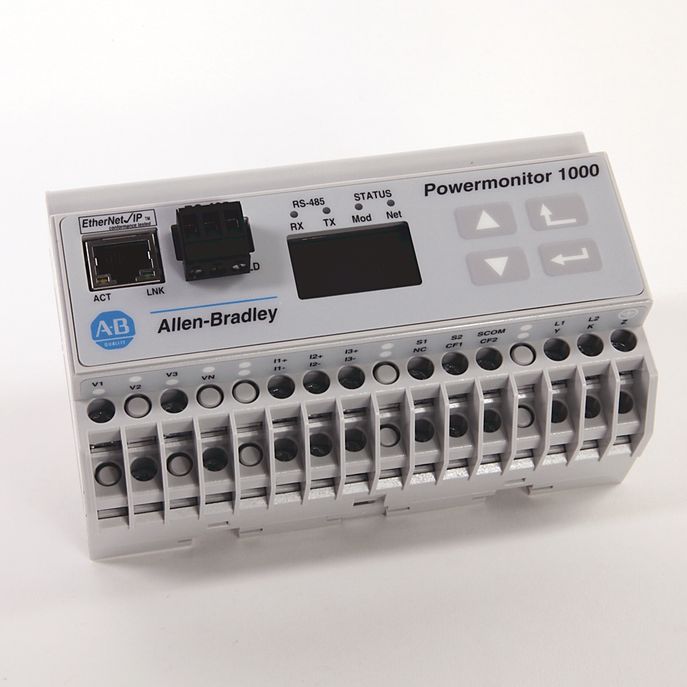
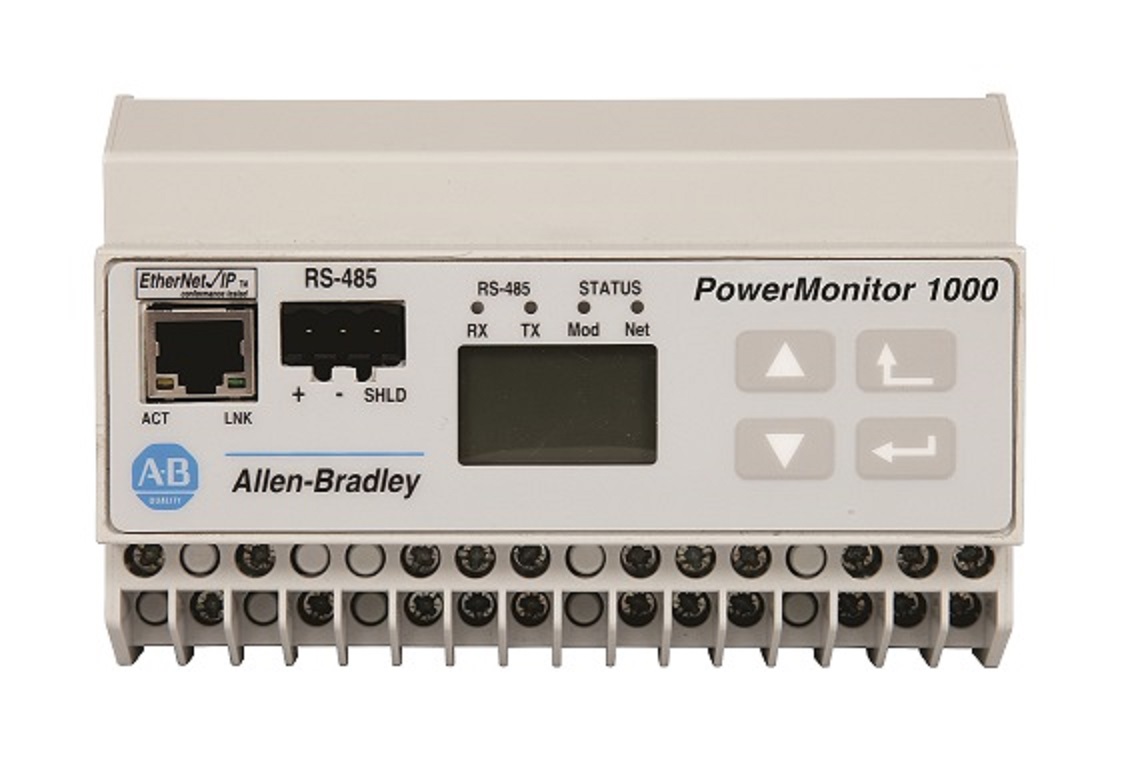
| Ethernet network port - standard RJ45 jack with status indicators |
Ethernet network port hardware is included on all models. the port functions only on units ordered with or upgraded to the Ethernet network. the following protocols and functions are supported. Ethernet/IP Modbus TCP HTML webpage for configuration and data access lnk indicator solid green: IP link established OFF : no link established act indicator flashing yellow: data present on Ethernet port OFF : no data activity present
|
| DIN rail clips |
Top and bottom clips for mounting unit on DIN rail
|
| Configuration lock wiring terminals |
Wire together to help prevent configuration changes
|
| LCD |
Unit configuration data display - not present on BC3 model
|
| LCD interface buttons |
Unit configuration data display navigation not present on BC3 model
|
| KYZ-output wiring terminals |
DPDT solid-state relay for signaling use - not present on BC3 model
|
| Mac ID label |
Aa:bb:cc:dd:ee:ff, used when assigning an IP address using DHCP, X, X, X
|
| Current sensing wiring terminals |
Nominal input current 5 A, Use current transformers (CTs) to connect to power system
|
| Serial port status indicators |
Tx indicator flashes yellow when data is being transmitted Rx indicator flashes yellow when data is being received
|
| Status-input wiring terminals Restore factory defaults wiring terminals (BC3) |
Two internally-powered inputs (TS3, EM3), S2 can be used for demand period synchronization (TS3, EM3), FD1 and FD2 can be used to restore factory default configuration (BC3).
|
| Serial port - three-pin RS-485 connector |
All models include RS-485 serial communication that supports the following protocols and functions. DF1 half-duplex slave, DF1 full-duplex, Modbus RTU slave, Configuration by using terminal emulation software, DH-485.
|
| Module and network status indicators |
Module indicator GREEN: normal ops Alternating RED/GREEN: performing self-test RED (solid or blinking): initial power-up or failed self-test. network indicator GREEN: Ethernet connection established Blinking GREEN: Ethernet port looking for a connection RED: duplicate IP address detected.
|
| Frequency |
Hz: Yes
|
|---|---|
| Reactive power (kVAR) |
True
|
| Current |
True
|
| Real power (kW) |
True
|
| Apparent power (kVA) |
True
|
| True power factor |
True
|
| Real power consumption (kWh) |
True
|
| Reactive power consumption (kVARh) |
True
|
| Apparent power consumption (kVAh) |
True
|
| Real power demand (kW) |
True
|
| Reactive power demand (kVAR) |
True
|
| Apparent power demand (kVA) |
True
|
| Demand power factor |
True
|
| Projected kW demand |
True
|
| Projected kVAR demand |
True
|
| Projected kVA demand |
True
|
| Voltage unbalance |
True
|
| Current unbalance |
True
|
| Voltage |
True
|
| Alarms |
True
|
|---|
| Description |
PowerMonitor 1000 energy, demand, and PowerMonitor with serial network communication
|
|---|---|
| Ampere meter |
True
|
| Blind power meter |
True
|
| Frequency meter |
True
|
| Pulse counter |
True
|
| Voltmeter |
True
|
| Effective power measurement device |
True
|
| Time of use log |
True
|
|---|---|
| Energy log |
True
|
| Minimum/maximum log |
True
|
| Load factor log |
True
|
| Unit status log |
True
|
| Alarm log |
True
|
| Digital output |
True
|
|---|---|
| Digital accuracy |
Class1
|
| Energy management meter w/Ethernet |
True
|
|---|
| Drawings | |
|---|---|
| Dimension Drawing (PDF) | Download (PDF) |
| 3D STP (STEP) Model | Download (ZIP) |
| 2D Drawing (PDF) | Download (PDF) |
| Product Drawing | Drawing (DXF) |
| Product Drawing | Drawing (DXF) |
| Drawings |
|---|
| Dimension Drawing (PDF) Download (PDF) |
| 3D STP (STEP) Model Download (ZIP) |
| 2D Drawing (PDF) Download (PDF) |
| Product Drawing Drawing (DXF) |
| Product Drawing Drawing (DXF) |
Sign in to your Rockwell Automation account to view and download technical drawings.
Sign In
| General | Publication |
|---|---|
| Product Profile | -- |
| Product Cutsheet | -- |
| User Manual | Publication |
|---|---|
| 1408-um002_-en-p | 1408-UM002 |
Looking for more documentation?
Find curated technical documentation for this product in the Technical Documentation Center, or search our full Literature Library.
Visit the Technical Documentation Center
Search the Literature Library
- UKCA DOC
This product was certified with the above certifications as of {}. Products sold before or after this date might carry different certifications. Please review the product label to check for the certifications your specific product carries.
Looking for more Technotes?
Find questions and answers from Rockwell Automation technical experts for this product in our Knowledgebase.
Search Knowledgebase
Technical Specifications
| Accuracy |
1.00%
|
|---|---|
| Communications |
EtherNet/IP
|
| Frequency Rating |
40-75Hz
|
| Interface |
Webpage
|
| Metering Voltage |
600VLL AC
|
| Output |
2 Digital Relays
|
| Vibration |
2.0 G @ 10…500 Hz
|
|---|---|
| Shock |
Operating : 30 G peak each axis
|
| Dielectric withstand |
UL61010, EN61010 pollution degree 2
|
| Storage temperature |
-40 to 85 °C
|
| Operating temperature |
-10 to 60 °C
|
| Humidity |
5...95% noncondensing
|
| Terminal blocks |
0.34…2.5 mm² (22 AWG), 75 °C (167 °F) min copper wire only recommended torque 0.8 N.m (7 in-lb)
|
| Control power |
85…264V AC, 47…63 Hz 125…250V DC 4VA maximum
|
|---|---|
| Current sense inputs: I1, I2, I3 |
Starting current : 5 mA
|
| Voltage sense inputs: V1, V2, V3, max |
Input current : 2 mA
|
| Voltage sense inputs: V1, V2, V3, min |
Input impedance : 5 MΩ
|
| Status inputs |
Contact closure (internal 24V DC)(except BC3)
|
|---|---|
| Configurable via webpage |
True
|
| Display (integrated LCD) |
True
|
| CIP energy object |
True
|
| Control power |
85…264V AC, 47…63 Hz 125…250V DC 4VA maximum
|
|---|---|
| Current sense inputs: I1, I2, I3 |
Starting current : 5 mA
|
| Voltage sense inputs: V1, V2, V3, max |
Input current : 2 mA
|
| Voltage sense inputs: V1, V2, V3, min |
Input impedance : 5 MΩ
|
| Control power and ground wiring terminals |
120…240V AC, 50…60 Hz
|
|---|---|
| Accuracy |
Voltage sense inputs: ±0.5% @ 25°C, 50/60 Hz, unity Power Factor, line-neutral rms : 347V nom / 15…399V
|
| Voltage sensing wiring terminals |
Direct connect up to 600V AC three-phase line-to-line, Maximum nominal line-to-ground voltage 347V, Use potential transformers (PTs) for higher voltages.
|
| Ethernet network port - standard RJ45 jack with status indicators |
Ethernet network port hardware is included on all models. the port functions only on units ordered with or upgraded to the Ethernet network. the following protocols and functions are supported. Ethernet/IP Modbus TCP HTML webpage for configuration and data access lnk indicator solid green: IP link established OFF : no link established act indicator flashing yellow: data present on Ethernet port OFF : no data activity present
|
| DIN rail clips |
Top and bottom clips for mounting unit on DIN rail
|
| Configuration lock wiring terminals |
Wire together to help prevent configuration changes
|
| LCD |
Unit configuration data display - not present on BC3 model
|
| LCD interface buttons |
Unit configuration data display navigation not present on BC3 model
|
| KYZ-output wiring terminals |
DPDT solid-state relay for signaling use - not present on BC3 model
|
| Mac ID label |
Aa:bb:cc:dd:ee:ff, used when assigning an IP address using DHCP, X, X, X
|
| Current sensing wiring terminals |
Nominal input current 5 A, Use current transformers (CTs) to connect to power system
|
| Serial port status indicators |
Tx indicator flashes yellow when data is being transmitted Rx indicator flashes yellow when data is being received
|
| Status-input wiring terminals Restore factory defaults wiring terminals (BC3) |
Two internally-powered inputs (TS3, EM3), S2 can be used for demand period synchronization (TS3, EM3), FD1 and FD2 can be used to restore factory default configuration (BC3).
|
| Serial port - three-pin RS-485 connector |
All models include RS-485 serial communication that supports the following protocols and functions. DF1 half-duplex slave, DF1 full-duplex, Modbus RTU slave, Configuration by using terminal emulation software, DH-485.
|
| Module and network status indicators |
Module indicator GREEN: normal ops Alternating RED/GREEN: performing self-test RED (solid or blinking): initial power-up or failed self-test. network indicator GREEN: Ethernet connection established Blinking GREEN: Ethernet port looking for a connection RED: duplicate IP address detected.
|
| Frequency |
Hz: Yes
|
|---|---|
| Reactive power (kVAR) |
True
|
| Current |
True
|
| Real power (kW) |
True
|
| Apparent power (kVA) |
True
|
| True power factor |
True
|
| Real power consumption (kWh) |
True
|
| Reactive power consumption (kVARh) |
True
|
| Apparent power consumption (kVAh) |
True
|
| Real power demand (kW) |
True
|
| Reactive power demand (kVAR) |
True
|
| Apparent power demand (kVA) |
True
|
| Demand power factor |
True
|
| Projected kW demand |
True
|
| Projected kVAR demand |
True
|
| Projected kVA demand |
True
|
| Voltage unbalance |
True
|
| Current unbalance |
True
|
| Voltage |
True
|
| Alarms |
True
|
|---|
| Description |
PowerMonitor 1000 energy, demand, and PowerMonitor with serial network communication
|
|---|---|
| Ampere meter |
True
|
| Blind power meter |
True
|
| Frequency meter |
True
|
| Pulse counter |
True
|
| Voltmeter |
True
|
| Effective power measurement device |
True
|
| Time of use log |
True
|
|---|---|
| Energy log |
True
|
| Minimum/maximum log |
True
|
| Load factor log |
True
|
| Unit status log |
True
|
| Alarm log |
True
|
| Digital output |
True
|
|---|---|
| Digital accuracy |
Class1
|
| Energy management meter w/Ethernet |
True
|
|---|
Drawings
| Drawings | |
|---|---|
| Dimension Drawing (PDF) | Download (PDF) |
| 3D STP (STEP) Model | Download (ZIP) |
| 2D Drawing (PDF) | Download (PDF) |
| Product Drawing | Drawing (DXF) |
| Product Drawing | Drawing (DXF) |
| Drawings |
|---|
| Dimension Drawing (PDF) Download (PDF) |
| 3D STP (STEP) Model Download (ZIP) |
| 2D Drawing (PDF) Download (PDF) |
| Product Drawing Drawing (DXF) |
| Product Drawing Drawing (DXF) |
Sign in to your Rockwell Automation account to view and download technical drawings.
Sign In
Documents
|
Product Profile
General
-- |
|
Product Cutsheet
General
-- |
|
1408-um002_-en-p
User Manual
1408-UM002 |
| General | Publication |
|---|---|
| Product Profile | -- |
| Product Cutsheet | -- |
| User Manual | Publication |
| 1408-um002_-en-p | 1408-UM002 |
Looking for more documentation?
Find curated technical documentation for this product in the Technical Documentation Center, or search our full Literature Library.
Visit the Technical Documentation Center
Search the Literature Library
Certifications
- UKCA DOC
This product was certified with the above certifications as of {}. Products sold before or after this date might carry different certifications. Please review the product label to check for the certifications your specific product carries.
Accessories
Technotes
Looking for more Technotes?
Find questions and answers from Rockwell Automation technical experts for this product in our Knowledgebase.
Search Knowledgebase
Loading
Copyright ©2026 Rockwell Automation, Inc.