View all Bulletin 100-K Miniature Contactors
Preferred
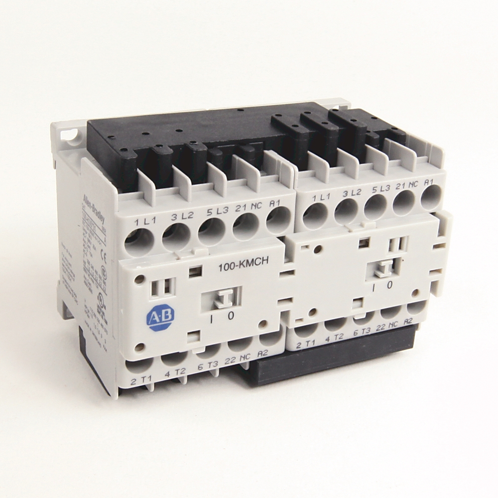
104-K05DJ02
IEC Miniature Reversing Contactor
| Contactor Size |
5 A
|
|---|---|
| Sub Brand |
IEC
|
| Voltage type for actuating |
DC
|
|---|---|
| Rated control supply voltage at AC 50 Hz |
0 V
|
| Rated control supply voltage at AC 60 Hz |
0 V
|
| Rated control supply voltage at DC |
24 V
|
| Rated impulse withstand voltage (Uimp) |
6 kV
|
| Current (Ie), max |
12 A
|
| Power dissipation by all circuits at Ie AC-3/400V |
0.3 W
|
| Main current circuit resistance |
2.2 mohm
|
| Current rating |
5 A
|
| Rated isolation voltage (Ui) |
690V per IEC
|
| Rated voltage (Ue) |
690V @ AC, 50/60 Hz
|
| Auxiliary contact configuration |
1 NC
|
| Rated filament current |
5A @ 230/240V, AC-5b
|
| Switching of motor load for home appliances |
6A @ 400V, AC-7b (50 Hz)
|
| Rated current (enclosed) |
9.8A @ 115V, 1-phase per UL/CSA
|
| Rated power (enclosed) |
3Hp @ 575V, 3-phase per UL/CSA
|
| General purpose current (enclosed) |
12 A per UL/CSA
|
| Switching of low inductive loads in home appliances |
20A @ 400V, AC-7a per IEC 61095 (50 Hz)
|
| Coil operating limits, pick-up |
(0.7...1.25) x Us DC (conventional)
|
| Coil operating limits, dropout |
(0.1...0.75) x Us DC (conventional)
|
| Coil operating time |
8...12 ms, opening delay @ integrated diode
|
| Short time withstand (Icw) |
60A @ 10s, 60 °C
|
| Coil consumption, hold-in |
Cold 3.0 W, warm 2.6 W DC (conventional)
|
| Switching frequency, max |
250 ops/h, AC-4 (approximately 200000 ops)
|
| Coil consumption, pick-up |
Cold 3.0 W, warm 2.6 W DC (conventional)
|
| Total power dissipation |
DC control: 2.9 W @ 400V, AC-3, Ie
|
| Switching of lamps |
Gas discharge lA, open: 18A @ 40°C, AC-5a
|
| Switching of hermetically sealed cooling compressor motors |
11A @ 400V, AC-8a (manual reset of overload release (50 Hz))
|
| Coil insulation class |
Class F per IEC 60085, Class 105 insulation system per UL 508
|
| Rating for switching AC motors |
3-poles: 2.2 kW @ 690V (AC-2, AC-3, AC-4), 3-phase (50 Hz)
|
| UL class K5 and RK5 fuses rating |
40A @ 600V, 5 kA available fault current per UL 508 and CSA 22.2 No. 14
|
| UL class CC and CSA HRCI-MISC fuses rating |
30A @ 600V, 50 kA available fault current per UL 508 and CSA 22.2 No. 14
|
| Coil voltage |
24V (17-30)V DC diode
|
| Rated operational current (Ie) |
8.5A @ 415V, Star-Delta starting (50 Hz)
|
| Rated operational power (Pe) |
8.3 kW @ 240V, AC-1 (50 Hz), ambient temperature 40 °C
|
| DIN fuses (gG, gL) current rating |
Type 2 (per IEC 60947-4-1): 16A @ 400V, 50 kA available fault current
|
| UL class J and CSA HRCI-J fuses rating |
30A @ 600V, 50 kA available fault current per UL 508 and CSA 22.2 No. 14
|
| Switching of power transformers |
Apparent power: 2 kVA @ 690V, AC-6a @ 50Hz (n = 30)
|
| Switching of DC loads |
3-poles in series: 6A @ 48/60V (Non-inductive or slightly inductive loads or resistance furnaces DC-1 at 60 °C)
|
| Contacts |
3 power poles with internal NC auxiliary contact
|
| Function |
Reversing contactor
|
| Conductor cross section per UL/CSA |
18
|
| Terminal type |
Screw terminals
|
| Rated coil frequency |
AC 50/60 Hz, DC
|
| Function or layout |
Nothing specified
|
| Vibration resistance |
IEC 60068-2
|
|---|---|
| Shock resistance |
IEC 60068-2
|
| Recommended torque |
10.6 in-lb
|
| Conductor cross section |
0.75...2.5 mm², 2 conductors @ main contact
|
| Lifespan |
Mechanical DC control: 15000000 ops
|
| Weight |
0.48 kg (1.06 lbs) reverse @ DC
|
| Type of electrical connection of main circuit |
Screw connection
|
| Auxiliary contacts |
IP2X
|
|---|---|
| Altitude of installation site, max |
2000 m (NN), per IEC 60947-4
|
| Ambient temperature |
Storage: -55...80 (-67...176)
|
| Degree of protection (IP) |
IP2X
|
| Optional overload relays |
Bimetallic
|
|---|---|
| Optional accessories |
Front-mount auxiliary contacts, surge suppressors, electronic timers, mechanical interlocks
|
| Features |
Mini-contactors, Uniform panel mounting dimensions, Panel mounting or mounting on 35 mm DIN Rail, Made of environmentally friendly materials
|
| Climatic withstand |
IEC 60068-2-30
|
|---|
| Drawings | |
|---|---|
| 3-Dimensional STEP model (STP) | Download (ZIP) |
| Product Drawing | Drawing (DXF) |
| Drawings |
|---|
| 3-Dimensional STEP model (STP) Download (ZIP) |
| Product Drawing Drawing (DXF) |
Sign in to your Rockwell Automation account to view and download technical drawings.
Sign In
| General | Publication |
|---|---|
| Product Cutsheet | -- |
| Technical Data | Publication |
|---|---|
| 100-td013_-en-p | 100-TD013 |
Looking for more documentation?
Find curated technical documentation for this product in the Technical Documentation Center, or search our full Literature Library.
Search the Literature Library
| Technotes |
|---|
Looking for more Technotes?
Find questions and answers from Rockwell Automation technical experts for this product in our Knowledgebase.
Search Knowledgebase
Technical Specifications
| Contactor Size |
5 A
|
|---|---|
| Sub Brand |
IEC
|
| Voltage type for actuating |
DC
|
|---|---|
| Rated control supply voltage at AC 50 Hz |
0 V
|
| Rated control supply voltage at AC 60 Hz |
0 V
|
| Rated control supply voltage at DC |
24 V
|
| Rated impulse withstand voltage (Uimp) |
6 kV
|
| Current (Ie), max |
12 A
|
| Power dissipation by all circuits at Ie AC-3/400V |
0.3 W
|
| Main current circuit resistance |
2.2 mohm
|
| Current rating |
5 A
|
| Rated isolation voltage (Ui) |
690V per IEC
|
| Rated voltage (Ue) |
690V @ AC, 50/60 Hz
|
| Auxiliary contact configuration |
1 NC
|
| Rated filament current |
5A @ 230/240V, AC-5b
|
| Switching of motor load for home appliances |
6A @ 400V, AC-7b (50 Hz)
|
| Rated current (enclosed) |
9.8A @ 115V, 1-phase per UL/CSA
|
| Rated power (enclosed) |
3Hp @ 575V, 3-phase per UL/CSA
|
| General purpose current (enclosed) |
12 A per UL/CSA
|
| Switching of low inductive loads in home appliances |
20A @ 400V, AC-7a per IEC 61095 (50 Hz)
|
| Coil operating limits, pick-up |
(0.7...1.25) x Us DC (conventional)
|
| Coil operating limits, dropout |
(0.1...0.75) x Us DC (conventional)
|
| Coil operating time |
8...12 ms, opening delay @ integrated diode
|
| Short time withstand (Icw) |
60A @ 10s, 60 °C
|
| Coil consumption, hold-in |
Cold 3.0 W, warm 2.6 W DC (conventional)
|
| Switching frequency, max |
250 ops/h, AC-4 (approximately 200000 ops)
|
| Coil consumption, pick-up |
Cold 3.0 W, warm 2.6 W DC (conventional)
|
| Total power dissipation |
DC control: 2.9 W @ 400V, AC-3, Ie
|
| Switching of lamps |
Gas discharge lA, open: 18A @ 40°C, AC-5a
|
| Switching of hermetically sealed cooling compressor motors |
11A @ 400V, AC-8a (manual reset of overload release (50 Hz))
|
| Coil insulation class |
Class F per IEC 60085, Class 105 insulation system per UL 508
|
| Rating for switching AC motors |
3-poles: 2.2 kW @ 690V (AC-2, AC-3, AC-4), 3-phase (50 Hz)
|
| UL class K5 and RK5 fuses rating |
40A @ 600V, 5 kA available fault current per UL 508 and CSA 22.2 No. 14
|
| UL class CC and CSA HRCI-MISC fuses rating |
30A @ 600V, 50 kA available fault current per UL 508 and CSA 22.2 No. 14
|
| Coil voltage |
24V (17-30)V DC diode
|
| Rated operational current (Ie) |
8.5A @ 415V, Star-Delta starting (50 Hz)
|
| Rated operational power (Pe) |
8.3 kW @ 240V, AC-1 (50 Hz), ambient temperature 40 °C
|
| DIN fuses (gG, gL) current rating |
Type 2 (per IEC 60947-4-1): 16A @ 400V, 50 kA available fault current
|
| UL class J and CSA HRCI-J fuses rating |
30A @ 600V, 50 kA available fault current per UL 508 and CSA 22.2 No. 14
|
| Switching of power transformers |
Apparent power: 2 kVA @ 690V, AC-6a @ 50Hz (n = 30)
|
| Switching of DC loads |
3-poles in series: 6A @ 48/60V (Non-inductive or slightly inductive loads or resistance furnaces DC-1 at 60 °C)
|
| Contacts |
3 power poles with internal NC auxiliary contact
|
| Function |
Reversing contactor
|
| Conductor cross section per UL/CSA |
18
|
| Terminal type |
Screw terminals
|
| Rated coil frequency |
AC 50/60 Hz, DC
|
| Function or layout |
Nothing specified
|
| Vibration resistance |
IEC 60068-2
|
|---|---|
| Shock resistance |
IEC 60068-2
|
| Recommended torque |
10.6 in-lb
|
| Conductor cross section |
0.75...2.5 mm², 2 conductors @ main contact
|
| Lifespan |
Mechanical DC control: 15000000 ops
|
| Weight |
0.48 kg (1.06 lbs) reverse @ DC
|
| Type of electrical connection of main circuit |
Screw connection
|
| Auxiliary contacts |
IP2X
|
|---|---|
| Altitude of installation site, max |
2000 m (NN), per IEC 60947-4
|
| Ambient temperature |
Storage: -55...80 (-67...176)
|
| Degree of protection (IP) |
IP2X
|
| Optional overload relays |
Bimetallic
|
|---|---|
| Optional accessories |
Front-mount auxiliary contacts, surge suppressors, electronic timers, mechanical interlocks
|
| Features |
Mini-contactors, Uniform panel mounting dimensions, Panel mounting or mounting on 35 mm DIN Rail, Made of environmentally friendly materials
|
| Climatic withstand |
IEC 60068-2-30
|
|---|
Drawings
| Drawings | |
|---|---|
| 3-Dimensional STEP model (STP) | Download (ZIP) |
| Product Drawing | Drawing (DXF) |
| Drawings |
|---|
| 3-Dimensional STEP model (STP) Download (ZIP) |
| Product Drawing Drawing (DXF) |
Sign in to your Rockwell Automation account to view and download technical drawings.
Sign In
Documents
|
Product Cutsheet
General
-- |
|
100-td013_-en-p
Technical Data
100-TD013 |
| General | Publication |
|---|---|
| Product Cutsheet | -- |
| Technical Data | Publication |
| 100-td013_-en-p | 100-TD013 |
Looking for more documentation?
Find curated technical documentation for this product in the Technical Documentation Center, or search our full Literature Library.
Search the Literature Library
Accessories
Alternative Products
Technotes
| Technotes |
|---|
Looking for more Technotes?
Find questions and answers from Rockwell Automation technical experts for this product in our Knowledgebase.
Search Knowledgebase
Copyright ©2026 Rockwell Automation, Inc.