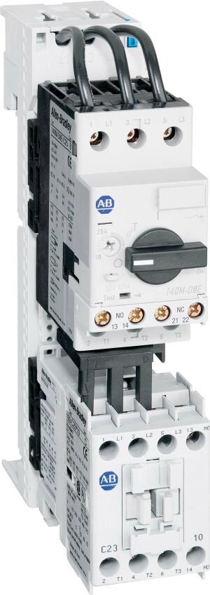
103S-ASD2-CB25D
1.6-2.5 A Combination Starter
Rockwell Automation announces that as of February 16, 2024, the 1.6-2.5 A Combination Starter will be discontinued and no longer available for sale. Customers are encouraged to remove references to the affected product(s)
Discontinued Date:
February 16, 2024
Replacement Category:
Direct Replacement
Replacement Product:
190A-SC09D10-CB25D-SP
[https://www.rockwellautomation.com/en-us/products/details.190A-SC09D10-CB25D-SP.html]
Product at a glance
| Number of auxiliary contacts as normally open contact |
1
|
|---|---|
| Voltage type for actuating |
AC
|
| Suitable for emergency stop |
True
|
| External reset possible |
True
|
| With short-circuit release |
True
|
| Rated control supply voltage at AC 50 Hz |
110 V
|
| Rated control supply voltage at AC 60 Hz |
120 V
|
| Release class |
CLASS 10
|
| Overload release current setting |
1.6 A
|
| Type of motor starter |
Direct online starter (DOL)
|
| Contactor size |
100-C09
|
| Contactor auxiliary contacts |
1 NO
|
| Style |
141A ISO bus bar system
|
| Fuse or circuit breaker per NEC, max |
450 A with 100-C/104-C contactors on standard bus bar modules
|
| Circuit breaker auxiliary and trip contacts |
Internal circuit-breaker auxiliary contact 2 NO
|
| Side mount auxiliary and trip contacts |
Without auxiliary and trip contacts
|
| Short-circuit current as a IEC (Type 1 coordination), max |
8kA @ 690V AC, 50 Hz (with 100-C/104-C contactors on standard bus bar modules)
|
| Short-circuit current as a UL508 motor controller in group motor installations (Type 2 coordination), max |
65kA @ 480V AC, 60 Hz (with 100-C/104-C contactors on standard bus bar modules)
|
| Short-circuit current as a UL508 motor controller in group motor installations (Type 1 coordination), max |
65kA @ 480V AC, 60 Hz (with 100-C/104-C contactors on standard bus bar modules)
|
| IEC kW ratings |
1.8 kW @ 690V AC @ 50Hz (with 100-C/104-C contactors on standard bus bar modules)
|
| Short-circuit current as a UL508 self-protected Type E combination motor controller, max |
65 kA @ 480Y/277V AC @ 60Hz (with 100-C/104-C contactors on standard bus bar modules)
|
| Short-circuit current as a UL508 Type F combination motor controller (Type 2 coordination), max |
65 kA @ 480Y/277V AC @ 60Hz (with 100-C/104-C contactors on standard bus bar modules)
|
| Short-circuit current as a UL508 Type F combination motor controller (Type 1 coordination), max |
65 kA @ 480Y/277V AC @ 60Hz (with 100-C/104-C contactors on standard bus bar modules)
|
| Short-circuit current as a IEC (Type 2 coordination), max |
8kA @ 690V AC, 50 Hz (with 100-C/104-C contactors on standard bus bar modules)
|
| Hp ratings as a UL508 Type F combination motor controller |
3/4...1.5Hp @ 460V AC, 60 Hz (with 100-C/104-C contactors on standard bus bar modules)
|
| Hp ratings as a UL508 self-protected Type E combination motor controller |
3/4...1.5Hp @ 460V AC, 60 Hz (with 100-C/104-C contactors on standard bus bar modules)
|
| Hp ratings as a UL508 motor controller in group motor installations |
3/4...1.5Hp @ 460V AC, 60 Hz (with 100-C/104-C contactors on standard bus bar modules)
|
| Temperature compensated overload protection |
True
|
| Type of electrical connection of main circuit |
Screw connection
|
| Type of electrical connection for auxiliary- and control current circuit |
Screw connection
|
| Rail mounting possible |
True
|
|---|
| Width, approx |
ISO busbar mount: 54 mm
|
|---|---|
| Height, approx |
ISO busbar mount: 241.5 mm
|
| Circuit breaker frame size |
140M-C2E high break (Type E - standard version, magnetic + thermal)
|
| Drawings | |
|---|---|
| Dimension Drawing (PDF) | Download (PDF) |
| Drawings |
|---|
| Dimension Drawing (PDF) Download (PDF) |
| Type | Resource | Publication |
|---|---|---|
| General | Wiring Diagram ANSI Style (PDF) | -- |
| General | Product Cutsheet | -- |
| General | Short Circuit Ratings Data Sheet | -- |
| General | Wiring Diagram IEC Style (PDF) | -- |
| Technical Data | 100-td013_-en-p | 100-TD013 |
Looking for more documentation?
Find curated technical documentation for this product in the Technical Documentation Center, or search our full Literature Library.
Search the Literature Library
Looking for more Technotes?
Find questions and answers from Rockwell Automation technical experts for this product in our Knowledgebase.
Search Knowledgebase
Technical Specifications
| Number of auxiliary contacts as normally open contact |
1
|
|---|---|
| Voltage type for actuating |
AC
|
| Suitable for emergency stop |
True
|
| External reset possible |
True
|
| With short-circuit release |
True
|
| Rated control supply voltage at AC 50 Hz |
110 V
|
| Rated control supply voltage at AC 60 Hz |
120 V
|
| Release class |
CLASS 10
|
| Overload release current setting |
1.6 A
|
| Type of motor starter |
Direct online starter (DOL)
|
| Contactor size |
100-C09
|
| Contactor auxiliary contacts |
1 NO
|
| Style |
141A ISO bus bar system
|
| Fuse or circuit breaker per NEC, max |
450 A with 100-C/104-C contactors on standard bus bar modules
|
| Circuit breaker auxiliary and trip contacts |
Internal circuit-breaker auxiliary contact 2 NO
|
| Side mount auxiliary and trip contacts |
Without auxiliary and trip contacts
|
| Short-circuit current as a IEC (Type 1 coordination), max |
8kA @ 690V AC, 50 Hz (with 100-C/104-C contactors on standard bus bar modules)
|
| Short-circuit current as a UL508 motor controller in group motor installations (Type 2 coordination), max |
65kA @ 480V AC, 60 Hz (with 100-C/104-C contactors on standard bus bar modules)
|
| Short-circuit current as a UL508 motor controller in group motor installations (Type 1 coordination), max |
65kA @ 480V AC, 60 Hz (with 100-C/104-C contactors on standard bus bar modules)
|
| IEC kW ratings |
1.8 kW @ 690V AC @ 50Hz (with 100-C/104-C contactors on standard bus bar modules)
|
| Short-circuit current as a UL508 self-protected Type E combination motor controller, max |
65 kA @ 480Y/277V AC @ 60Hz (with 100-C/104-C contactors on standard bus bar modules)
|
| Short-circuit current as a UL508 Type F combination motor controller (Type 2 coordination), max |
65 kA @ 480Y/277V AC @ 60Hz (with 100-C/104-C contactors on standard bus bar modules)
|
| Short-circuit current as a UL508 Type F combination motor controller (Type 1 coordination), max |
65 kA @ 480Y/277V AC @ 60Hz (with 100-C/104-C contactors on standard bus bar modules)
|
| Short-circuit current as a IEC (Type 2 coordination), max |
8kA @ 690V AC, 50 Hz (with 100-C/104-C contactors on standard bus bar modules)
|
| Hp ratings as a UL508 Type F combination motor controller |
3/4...1.5Hp @ 460V AC, 60 Hz (with 100-C/104-C contactors on standard bus bar modules)
|
| Hp ratings as a UL508 self-protected Type E combination motor controller |
3/4...1.5Hp @ 460V AC, 60 Hz (with 100-C/104-C contactors on standard bus bar modules)
|
| Hp ratings as a UL508 motor controller in group motor installations |
3/4...1.5Hp @ 460V AC, 60 Hz (with 100-C/104-C contactors on standard bus bar modules)
|
| Temperature compensated overload protection |
True
|
| Type of electrical connection of main circuit |
Screw connection
|
| Type of electrical connection for auxiliary- and control current circuit |
Screw connection
|
| Rail mounting possible |
True
|
|---|
| Width, approx |
ISO busbar mount: 54 mm
|
|---|---|
| Height, approx |
ISO busbar mount: 241.5 mm
|
| Circuit breaker frame size |
140M-C2E high break (Type E - standard version, magnetic + thermal)
|
Drawings
| Drawings | |
|---|---|
| Dimension Drawing (PDF) | Download (PDF) |
| Drawings |
|---|
| Dimension Drawing (PDF) Download (PDF) |
Documents
|
Wiring Diagram ANSI Style (PDF)
General
-- |
|
Product Cutsheet
General
-- |
|
Short Circuit Ratings Data Sheet
General
-- |
|
Wiring Diagram IEC Style (PDF)
General
-- |
|
100-td013_-en-p
Technical Data
100-TD013 |
| Type | Resource | Publication |
|---|---|---|
| General | Wiring Diagram ANSI Style (PDF) | -- |
| General | Product Cutsheet | -- |
| General | Short Circuit Ratings Data Sheet | -- |
| General | Wiring Diagram IEC Style (PDF) | -- |
| Technical Data | 100-td013_-en-p | 100-TD013 |
Looking for more documentation?
Find curated technical documentation for this product in the Technical Documentation Center, or search our full Literature Library.
Search the Literature Library
Alternative Products
Technotes
Looking for more Technotes?
Find questions and answers from Rockwell Automation technical experts for this product in our Knowledgebase.
Search Knowledgebase
Loading
Copyright ©2025 Rockwell Automation, Inc.