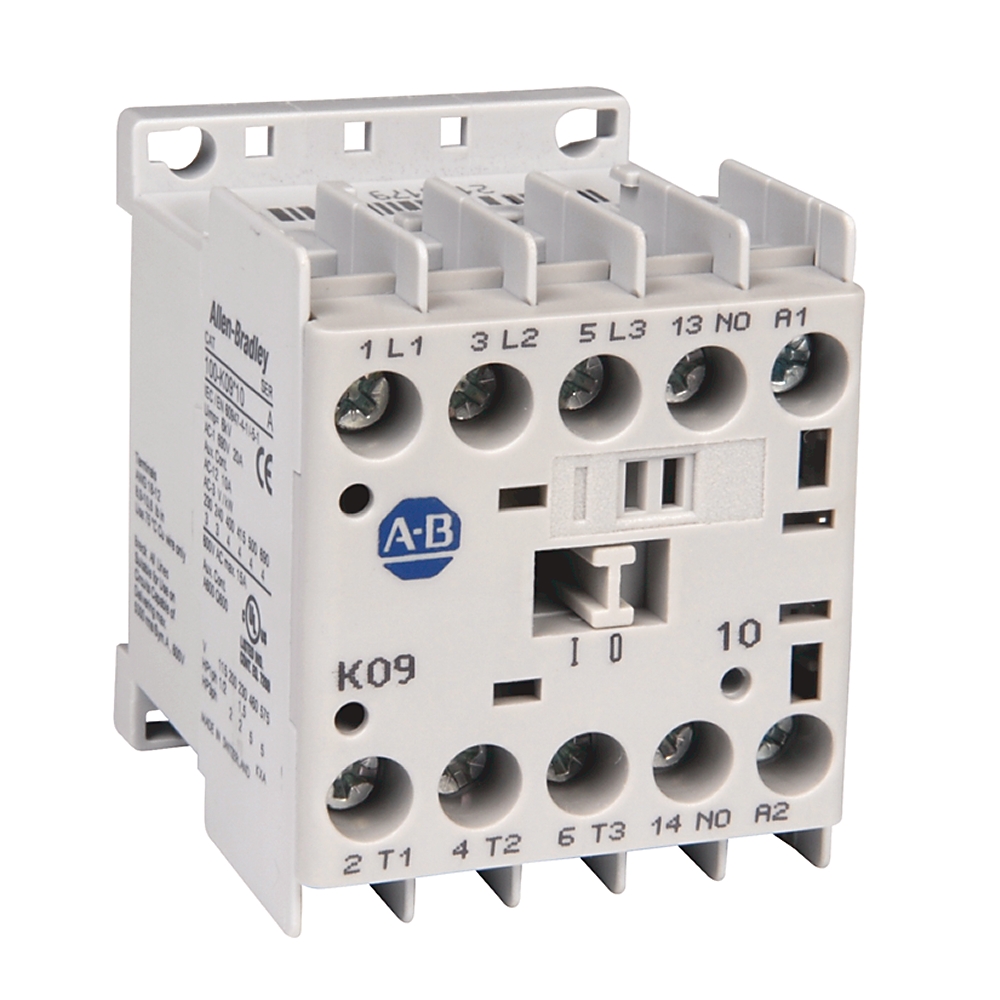
IEC 9 A Miniature Contactor
| Unique Product Identifier |
100-K09KJ10
|
|---|---|
| UPC |
662074491292
|
| Estimated Lead Time |
5 days
|
| Standard Warranty Duration |
1 year See details |
| Country of Origin |
Multiple
|
The information provided by Rockwell Automation on www.rockwellautomation.com (the “Site”) is for demonstration purposes only and may be incomplete or inaccurate. All information is provided “as is”, and Rockwell Automation makes no representations or warranties of any kind, express or implied, regarding the accuracy, adequacy, validity, reliability, or completeness of any information on the Site. Use of this information is at your own risk.
| Contact Configuration |
1 N.O.,3 N.O. Poles
|
|---|---|
| Contactor Size |
9 A
|
| Special Features |
Screw Type Terminals
|
| Sub Brand |
IEC
|
| Voltage type for actuating |
AC
|
|---|---|
| Rated control supply voltage at AC 50 Hz |
24 V
|
| Rated control supply voltage at AC 60 Hz |
24 V
|
| Rated control supply voltage at DC |
0 V
|
| Type of electrical connection of main circuit |
Screw connection
|
| Rated impulse withstand voltage (Uimp) |
6 kV
|
| Optional overload relays |
Bimetallic
|
| Main current circuit resistance |
2.2 mΩ
|
| Power dissipation (all circuits) |
0.9 W @ 400V, AC-3, Ie
|
| Rated filament current |
9A @ 230/240V, AC-5b
|
| Rated isolation voltage (Ui) |
IEC: 690V, UL, CSA: 600V
|
| Switching of motor load |
11A @ 400V, AC-7b (50 Hz)
|
| Packaging |
Single pack (quantity of 1)
|
| Auxiliary contacts |
IP2X
|
| Rated current (enclosed) |
9.8A @ 115V, 1-phase per UL/CSA
|
| Rated power (enclosed) |
5Hp @ 575V, 3-phase per UL/CSA
|
| Auxiliary contact configuration |
1 NO
|
| Capacitance, max |
750 µF @ short-circuit current of 10 kA
|
| General purpose current (enclosed) |
15 A per UL/CSA
|
| Operating time, closing delay |
6...12 ms DC (conventional)
|
| Switching of low inductive loads |
20A @ 400V, AC-7a per IEC 61095 (50 Hz)
|
| Short time withstand (Icw) |
96A @ 10s, 60 °C
|
| Operating time, opening delay |
8...12 ms with integrated diode
|
| Coil consumption, hold-in |
Cold 3.0 W, warm 2.6 W DC (conventional)
|
| Coil consumption, pick-up |
Cold 3.0 W, warm 2.6 W DC (conventional)
|
| Total power dissipation |
DC control: 3.5 W @ 400V, AC-3, Ie
|
| Operating limits, dropout |
(0.2...0.75) x Us @ 50 Hz, 60 Hz, 50/60 Hz
|
| Switching of lamps |
Gas discharge lA, open: 18A @ 40°C, AC-5a
|
| Insulation class of the coil |
Class F per IEC 60085, Class 105 insulation system per UL 508
|
| Rating for switching AC motors |
3-poles: 5Hp @ 575V (AC-2, AC-3, AC-4), 3-phase (60 Hz)
|
| Switching of hermetically sealed cooling compressor motors |
18A @ 400V, AC-8a (manual reset of overload release (50 Hz))
|
| Operating limits, pick-up |
(0.85...1.1) x Us @ 50 Hz, 60 Hz, 50/60 Hz
|
| UL class K5 and RK5 fuses rating |
40A @ 600V, 5 kA available fault current per UL 508 and CSA 22.2 No. 14
|
| DIN fuses (gG, gL) current rating |
Type 2 (per IEC 60947-4-1): 20A @ 400V, 50 kA available fault current
|
| Rated operational current (Ie) |
8.9A @ 690V, Star-Delta starting (50 Hz)
|
| UL class J and CSA HRCI-J fuses rating |
30A @ 600V, 50 kA available fault current per UL 508 and CSA 22.2 No. 14
|
| Switching of power transformers |
Apparent power: 4 kVA @ 500V, AC-6a @ 50Hz (n = 30)
|
| Rated operational power (Pe) |
8.3 kW @ 240V, AC-1 (50 Hz), ambient temperature 40 °C
|
| Switching of DC loads |
3-poles in series: 9A @ 48/60V (Non-inductive or slightly inductive loads or resistance furnaces DC-1 at 60 °C)
|
| Optional accessories |
Front-mount auxiliary contacts, surge suppressors, electronic timers, mechanical interlocks
|
| Features |
Mini-contactors, Uniform panel mounting dimensions, Panel mounting or mounting on 35 mm DIN Rail, Made of environmentally friendly materials
|
| UL class CC and CSA HRCI-MISC fuses rating |
30A @ 600V, 50 kA available fault current per UL 508 and CSA 22.2 No. 14
|
| Number of normally open contacts as main contact |
3
|
|---|---|
| Number of auxiliary contacts as normally open contact |
1
|
| Vibration resistance |
IEC 60068-2
|
| Shock resistance |
IEC 60068-2
|
| Altitude, max |
2000 m (NN) per IEC 60947-4
|
| Lifespan |
Mechanical DC control: 15000000 ops
|
| Switching frequency, max |
250 ops/h, AC-4 (approximately 200000 ops)
|
| Recommended torque |
10.6 in-lb
|
| Weight |
DC: 0.2 kg
|
| Conductor cross section |
Main contact, 2 conductor: 1...2.5 mm² + 1...4 mm²
|
| Protection class |
IP2X
|
| Climatic withstand |
IEC 60068-2-30
|
|---|---|
| Ambient temperature |
Storage: -55...80 (-67...176)
|
| Drawings | |
|---|---|
| 3-Dimensional STEP model (STP) | Download (ZIP) |
| Product Drawing | Drawing (DXF) |
| Drawings |
|---|
| 3-Dimensional STEP model (STP) Download (ZIP) |
| Product Drawing Drawing (DXF) |
| General | Publication |
|---|---|
| Technical Detail | 100-TD013 |
| Circuit Protection Device and SCCR Tables | -- |
| Product Cutsheet | -- |
| Technical Data | Publication |
|---|---|
| 140mp-td002_-en-p | 140MP-TD002 |
| Technotes |
|---|
Overview
| Unique Product Identifier |
100-K09KJ10
|
|---|---|
| UPC |
662074491292
|
| Estimated Lead Time |
5 days
|
| Standard Warranty Duration |
1 year See details |
| Country of Origin |
Multiple
|
The information provided by Rockwell Automation on www.rockwellautomation.com (the “Site”) is for demonstration purposes only and may be incomplete or inaccurate. All information is provided “as is”, and Rockwell Automation makes no representations or warranties of any kind, express or implied, regarding the accuracy, adequacy, validity, reliability, or completeness of any information on the Site. Use of this information is at your own risk.
Electrical & Connectivity
| Contact Configuration |
1 N.O.,3 N.O. Poles
|
|---|---|
| Contactor Size |
9 A
|
| Special Features |
Screw Type Terminals
|
| Sub Brand |
IEC
|
| Voltage type for actuating |
AC
|
|---|---|
| Rated control supply voltage at AC 50 Hz |
24 V
|
| Rated control supply voltage at AC 60 Hz |
24 V
|
| Rated control supply voltage at DC |
0 V
|
| Type of electrical connection of main circuit |
Screw connection
|
| Rated impulse withstand voltage (Uimp) |
6 kV
|
| Optional overload relays |
Bimetallic
|
| Main current circuit resistance |
2.2 mΩ
|
| Power dissipation (all circuits) |
0.9 W @ 400V, AC-3, Ie
|
| Rated filament current |
9A @ 230/240V, AC-5b
|
| Rated isolation voltage (Ui) |
IEC: 690V, UL, CSA: 600V
|
| Switching of motor load |
11A @ 400V, AC-7b (50 Hz)
|
| Packaging |
Single pack (quantity of 1)
|
| Auxiliary contacts |
IP2X
|
| Rated current (enclosed) |
9.8A @ 115V, 1-phase per UL/CSA
|
| Rated power (enclosed) |
5Hp @ 575V, 3-phase per UL/CSA
|
| Auxiliary contact configuration |
1 NO
|
| Capacitance, max |
750 µF @ short-circuit current of 10 kA
|
| General purpose current (enclosed) |
15 A per UL/CSA
|
| Operating time, closing delay |
6...12 ms DC (conventional)
|
| Switching of low inductive loads |
20A @ 400V, AC-7a per IEC 61095 (50 Hz)
|
| Short time withstand (Icw) |
96A @ 10s, 60 °C
|
| Operating time, opening delay |
8...12 ms with integrated diode
|
| Coil consumption, hold-in |
Cold 3.0 W, warm 2.6 W DC (conventional)
|
| Coil consumption, pick-up |
Cold 3.0 W, warm 2.6 W DC (conventional)
|
| Total power dissipation |
DC control: 3.5 W @ 400V, AC-3, Ie
|
| Operating limits, dropout |
(0.2...0.75) x Us @ 50 Hz, 60 Hz, 50/60 Hz
|
| Switching of lamps |
Gas discharge lA, open: 18A @ 40°C, AC-5a
|
| Insulation class of the coil |
Class F per IEC 60085, Class 105 insulation system per UL 508
|
| Rating for switching AC motors |
3-poles: 5Hp @ 575V (AC-2, AC-3, AC-4), 3-phase (60 Hz)
|
| Switching of hermetically sealed cooling compressor motors |
18A @ 400V, AC-8a (manual reset of overload release (50 Hz))
|
| Operating limits, pick-up |
(0.85...1.1) x Us @ 50 Hz, 60 Hz, 50/60 Hz
|
| UL class K5 and RK5 fuses rating |
40A @ 600V, 5 kA available fault current per UL 508 and CSA 22.2 No. 14
|
| DIN fuses (gG, gL) current rating |
Type 2 (per IEC 60947-4-1): 20A @ 400V, 50 kA available fault current
|
| Rated operational current (Ie) |
8.9A @ 690V, Star-Delta starting (50 Hz)
|
| UL class J and CSA HRCI-J fuses rating |
30A @ 600V, 50 kA available fault current per UL 508 and CSA 22.2 No. 14
|
| Switching of power transformers |
Apparent power: 4 kVA @ 500V, AC-6a @ 50Hz (n = 30)
|
| Rated operational power (Pe) |
8.3 kW @ 240V, AC-1 (50 Hz), ambient temperature 40 °C
|
| Switching of DC loads |
3-poles in series: 9A @ 48/60V (Non-inductive or slightly inductive loads or resistance furnaces DC-1 at 60 °C)
|
| Optional accessories |
Front-mount auxiliary contacts, surge suppressors, electronic timers, mechanical interlocks
|
| Features |
Mini-contactors, Uniform panel mounting dimensions, Panel mounting or mounting on 35 mm DIN Rail, Made of environmentally friendly materials
|
| UL class CC and CSA HRCI-MISC fuses rating |
30A @ 600V, 50 kA available fault current per UL 508 and CSA 22.2 No. 14
|
Physical Characteristics
| Number of normally open contacts as main contact |
3
|
|---|---|
| Number of auxiliary contacts as normally open contact |
1
|
| Vibration resistance |
IEC 60068-2
|
| Shock resistance |
IEC 60068-2
|
| Altitude, max |
2000 m (NN) per IEC 60947-4
|
| Lifespan |
Mechanical DC control: 15000000 ops
|
| Switching frequency, max |
250 ops/h, AC-4 (approximately 200000 ops)
|
| Recommended torque |
10.6 in-lb
|
| Weight |
DC: 0.2 kg
|
| Conductor cross section |
Main contact, 2 conductor: 1...2.5 mm² + 1...4 mm²
|
| Protection class |
IP2X
|
Compliance & Environment
| Climatic withstand |
IEC 60068-2-30
|
|---|---|
| Ambient temperature |
Storage: -55...80 (-67...176)
|
Drawings
| Drawings | |
|---|---|
| 3-Dimensional STEP model (STP) | Download (ZIP) |
| Product Drawing | Drawing (DXF) |
| Drawings |
|---|
| 3-Dimensional STEP model (STP) Download (ZIP) |
| Product Drawing Drawing (DXF) |
Documents
|
Technical Detail
General
100-TD013 |
|
Circuit Protection Device and SCCR Tables
General
-- |
|
Product Cutsheet
General
-- |
|
140mp-td002_-en-p
Technical Data
140MP-TD002 |
| General | Publication |
|---|---|
| Technical Detail | 100-TD013 |
| Circuit Protection Device and SCCR Tables | -- |
| Product Cutsheet | -- |
| Technical Data | Publication |
| 140mp-td002_-en-p | 140MP-TD002 |
Accessories
Alternative Products
Technotes
| Technotes |
|---|