
Manage Controller Communication
The controller provides connection resources whenever communication is established between two devices.
Connections are used when the system contains the following conditions or activities:
- I/O modules, communication modules, and adapters are present in the I/O configuration of the user project.
- Produced or consumed tags are configured in the user project.
- Connected Messages are executed in the user application.
- External devices, programming terminals, or HMIs communicate with the controller.
When configuring your control system, you must account for the number of
EtherNet/IP™
nodes you include in the I/O configuration tree in your project. The following table shows the maximum number of EtherNet/IP™
nodes that are supported for each controller.Cat. No. | Version 28 | Version 29 | Version 30 | Version 31 or later | Version 36 or later |
|---|---|---|---|---|---|
1756-L81E, 1756-L81EK, 1756-L81E-NSE, 1756-L81EXT, 1756-L81EP | — | 60 | 100 | 100 | 100 |
1756-L82E, 1756-L82EK, 1756-L82E-NSE, 1756-L82EXT | — | 80 | 175 | 175 | 175 |
1756-L83E, 1756-L83EK, 1756-L83E-NSE, 1756-L83EXT, 1756-L83EP | 100 | 100 | 250 | 250 | 250 |
1756-L84E, 1756-L84EK, 1756-L84E-NSE, 1756-L84EXT | — | 150 | 250 | 250 | 250 |
1756-L85E, 1756-L85EK, 1756-L85E-NSE, 1756-L85EXT, 1756-L85EP | 300 | 300 | 300 | 300 | 300 |
1756-L81ES, 1756-L81ESK, 1756-L81EXTS | — | — | — | 100 | 100 |
1756-L82ES, 1756-L82ESK, 1756-L82EXTS | — | — | — | 175 | 175 |
1756-L83ES, 1756-L83ESK, 1756-L83EXTS | — | — | — | 250 | 250 |
1756-L84ES, 1756-L84ESK, 1756-L84EXTS | — | — | — | 250 | 250 |
1756-L85ES | — | — | — | — | 300 |
Cat. No. | Version 28 | Version 29 | Version 30 | Version 31 or later | Version 36 or later |
|---|---|---|---|---|---|
1756-L81ES, 1756-L81ESK, 1756-L81EXTS | — | — | — | 100 | 100 |
1756-L82ES, 1756-L82ESK, 1756-L82EXTS | — | — | — | 175 | 175 |
1756-L83ES, 1756-L83ESK, 1756-L83EXTS | — | — | — | 250 | 250 |
1756-L84ES, 1756-L84ESK, 1756-L84EXTS | — | — | — | 250 | 250 |
1756-L85ES | — | — | — | — | 300 |
With firmware revision 29 or later, the Capacity tab on the Controllers Properties dialog box keeps a running count as you add nodes to the I/O configuration tree.
Maximum Number of Ethernet Nodes

Devices Included in the Node Count
Any
EtherNet/IP™
devices that you add to the I/O configuration section are counted toward the controller node limits. The following are examples of devices that must be counted:- Remote communication adapters
- Remote controllers
- Devices with an embedded EtherNet/IP port
- EtherNet/IP™devices that connect to a communication module in the local chassis, even though the communication module in the local chassis does not count as a node
- HMI devices that are included in the I/O configuration section
- Third-party devices that are directly connected to theEtherNet/IP™network
Devices Excluded from the Node Count
When considering the
EtherNet/IP™
node limitation of a ControlLogix®
5580 controller, you do not count Ethernet devices that exist on the EtherNet/IP™
network but are not added to the I/O configuration section of the project. The following devices are not added to the I/O configuration section in your project and are not counted among the total number of nodes:
- Computer
- Communication modules in the local chassis
- HMIs that are not added to the I/O configuration section
- Devices that are the target of MSG Instructions
- Standard Ethernet devices with which the controller communicates via a socket interface
The following example shows four nodes in the I/O tree.
Ethernet Nodes Example
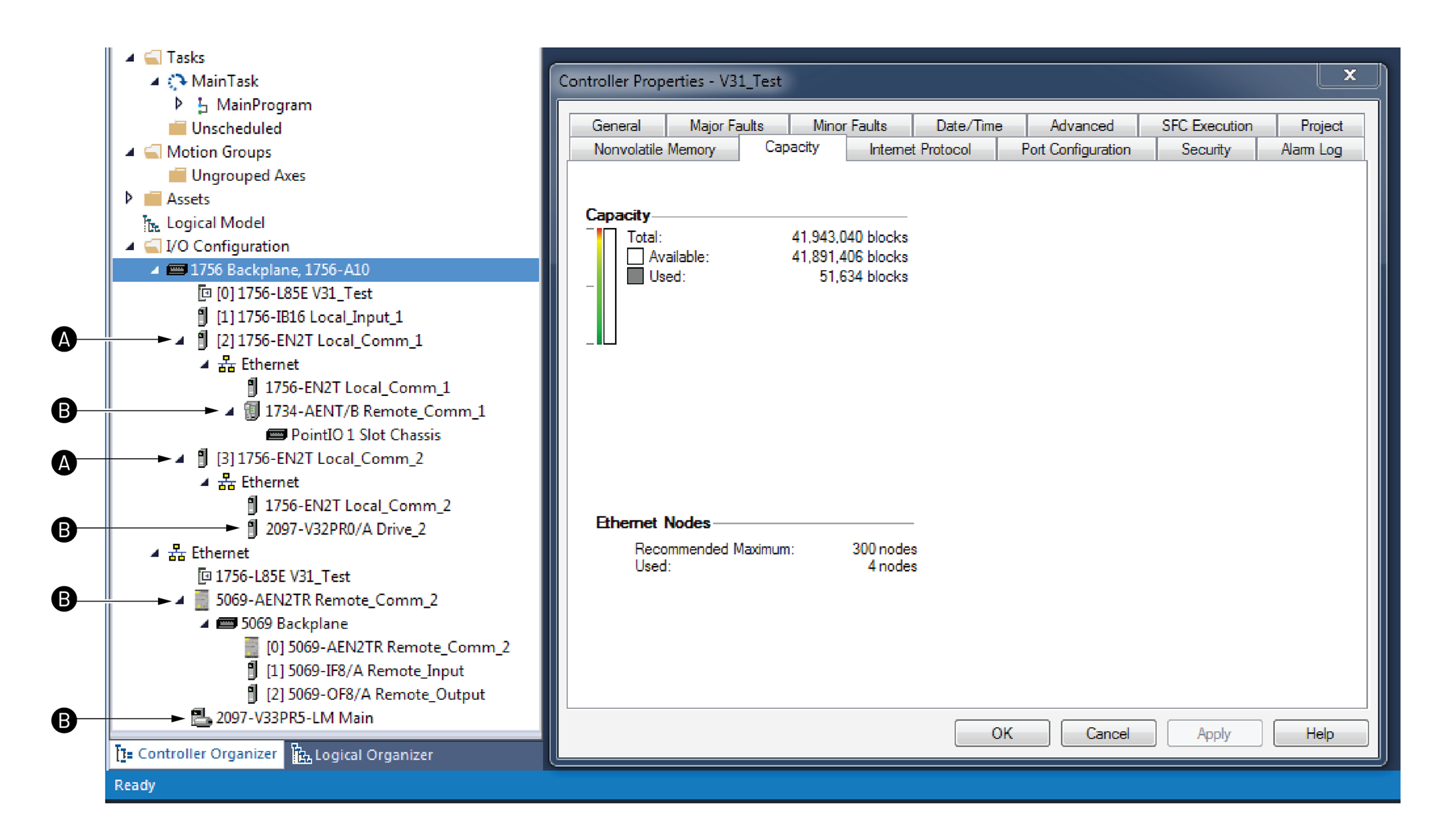
Item | Description |
|---|---|
A | Not a node. Module is in the local chassis. |
B | Node |
Provide Feedback