FFL and FFU instruction timing diagrams
The following timing diagram examples describe execution scenarios for the FFL (FIFO load) and FFU (FIFO unload) instructions.
Successful FFL execution followed by successful FFU execution
Successful FFL execution followed by successful FFU execution
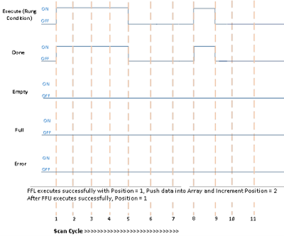
Scan Cycle | Description |
|---|---|
1 | Rung condition becomes TRUE when:
|
2,3,4 | No change in rung condition. |
5 | Rung condition becomes FALSE when:
|
6, 7 | No change in rung condition.
|
8 | Rung goes TRUE when:
|
9 | No change in rung condition.
|
10, 11 | No change in rung condition. |
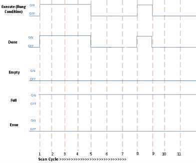
Successful execution when the Empty bit is TRUE
Successful execution when the Empty bit is TRUE

Scan Cycle | Description |
|---|---|
1 | Rung condition becomes TRUE when:
|
2,3,4 | No change in rung condition. |
5 | Rung condition becomes FALSE when:
|
6, 7 | No change in rung condition. |
8 | Rung goes TRUE when:
|
9 | Rung condition becomes FALSE when:
|
10, 11 | No change in rung condition. |
Successful execution when the Empty bit is TRUE
Successful execution when the Empty bit is TRUE
Scan Cycle | Description |
|---|---|
1 | Rung condition becomes TRUE when:
|
2,3,4 | No change in rung condition. |
5 | Rung condition becomes FALSE when:
|
6, 7 | No change in rung condition. |
8 | Rung goes TRUE when:
|
9 | Rung condition becomes FALSE when:
|
10, 11 | No change in rung condition. |
Error encountered during FFL and FFU execution
Error encountered during FFL and FFU execution
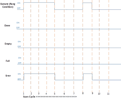
Scan Cycle | Description |
|---|---|
1 | Rung condition becomes TRUE when:
|
2,3,4 | No change in rung condition. |
5 | Rung condition becomes FALSE when:
|
6, 7 | No change in rung condition. |
8 | Rung goes TRUE when:
|
9 | Rung condition becomes FALSE when:
|
10, 11 | No change in rung condition. |
Provide Feedback