COM_IO_WDOG

The COM_IO_WDOG instruction monitors external messaging to controller inputs and outputs.
For example, if the CIP write command to variable _IO_EM_DO_00 is not received over EtherNet/IP within the configured timeout, the watch dog timer will expire and all controller outputs are reset.
EtherNet/IP, Modbus TCP, and Modbus RTU protocols are supported.
Languages supported: Function block diagram, ladder diagram, structured text.
This instruction applies to the L20E, L50E, and L70E controllers. The instruction is supported when the firmware revision is 12.00 or later.
COM_IO_WDOG
COM_IO_WDOG
TIP:
  • Although multiple instances of the instruction can exist, only one instance can be enabled. Otherwise, an error with ErrorID set to 2 will occur.
  • Only controller embedded, plug-in, and expansion digital I/Os are supported.
COM_IO_WDOG parameters
Parameter
Parameter Type
Data Type
Description
Enable
Input
BOOL
  • TRUE. Three cases of the TRUE condition are as follows:
    • On rising edge of TRUE, the function block starts to execute. Status bit is set to 0 and the rest of the bits are cleared. Then, the following error conditions are verified. If no errors occur, it proceeds to the next step.
      • If PresetValue is less than one second, Error is set to TRUE and ErrorID is set to 1, Status bit 4 is set, and TimeOut and ElapsedTime are cleared.
      • If the timer is already acquired by the other instance, Error is set to TRUE and ErrorID is set to 2, Status bit 4 is set, and TimeOut and ElapsedTime are cleared.
    • PresetTime > ElapseTime. When Enable is set to TRUE and the function block starts to execute. Check if any commands are received. If any commands are received, reset the timer immediately. Set ElapsedTime to 0 and set Status bit 2. The rest of the bits are cleared. If no commands are received, set Status bit 1 and the rest of the bits are cleared.
    • PresetTime = ElapsedTime. When Enable is set to TRUE and the function block starts to execute. Check if any commands are received. If received, reset the timer immediately. Set ElapsedTime to 0 and set the Status bit 2. The rest of the bits are cleared. Else set the TimeOut bit, set the Status bit 3 and the rest of the bits are cleared. Set the internal variable to clear the digital outputs at the end of the scan if the configured action is to clear all the digital outputs at the end of the scan.
  • FALSE: The instruction does not execute and function block outputs are cleared.
OutputClr
Input
BOOL
  • 0: Do nothing if timeout occurs.
  • 1: Clear all the digital outputs at the end of the scan (Embedded, EXIO and UPM) if timeout occurs.
PT
Input
TIME
Duration to wait before timeout.
The value for a timeout cannot be less than one second, or an error occurs. The maximum value for PresetTime can be the maximum value within TIME data type.
TimeOut
Output
BOOL
  • TRUE: ElapsedTime equals to PresetTime.
  • FALSE: Enable is set to FALSE; the timer is not elapsed or an error occurred.
ET
Output
TIME
The current elapsed time.
The possible values range is from 0 ms through 1193h2m47s294ms.
Status
Output
USINT
Status of the function block.
  • Bit 0: Enable
  • Bit 1: Timer is running. No output or input has been received.
  • Bit 2: The output or input command has been received.
  • Bit 3: Timeout occurred. No output or input command has been received.
  • Bit 4: Error occurred.
  • Other bits are reserved.
Error
Output
BOOL
Indicates an error.
ErrorID
Output
USINT
When an error occurs, ErrorID contains the error code.
COM_IO_WDOG error codes
ErrorID Code
Error Description
1
The PresetTime is less than one second.
2
Another COM_IO_WDOG function block instance is already executing.

COM_IO_WDOG examples

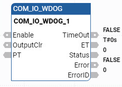
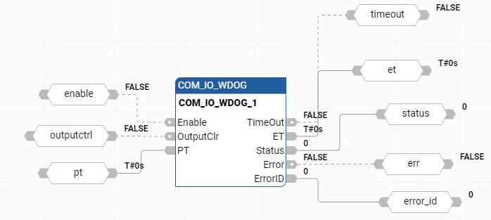
COM_IO_WDOG function block diagram example
COM_IO_WDOG ladder diagram example
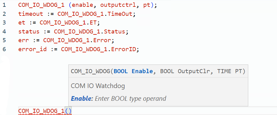
COM_IO_WDOG structured text example
Provide Feedback
Have questions or feedback about this documentation? Please submit your feedback here.
Normal