Monitor GuardLogix Safety Status
You can use the following to monitor the controller status:
- Safety partner and task status in the controller properties
- Safety I/O status
Safety Partner and Safety Task Status
The status of the safety partner and safety task appears on the Safety tab of the controller properties.
Safety Task Status
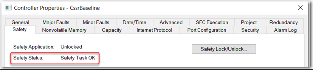
The following statuses can appear in the Safety Status field:
- Safety partner is missing or unavailable (SIL 3).
- Safety partner hardware is incompatible with the primary controller.
- Safety partner firmware is incompatible with the primary controller.
- Safety task inoperable.
- Safety task OK.
Except for the status 'Safety Task OK', the statuses indicate that a nonrecoverable safety fault exists.
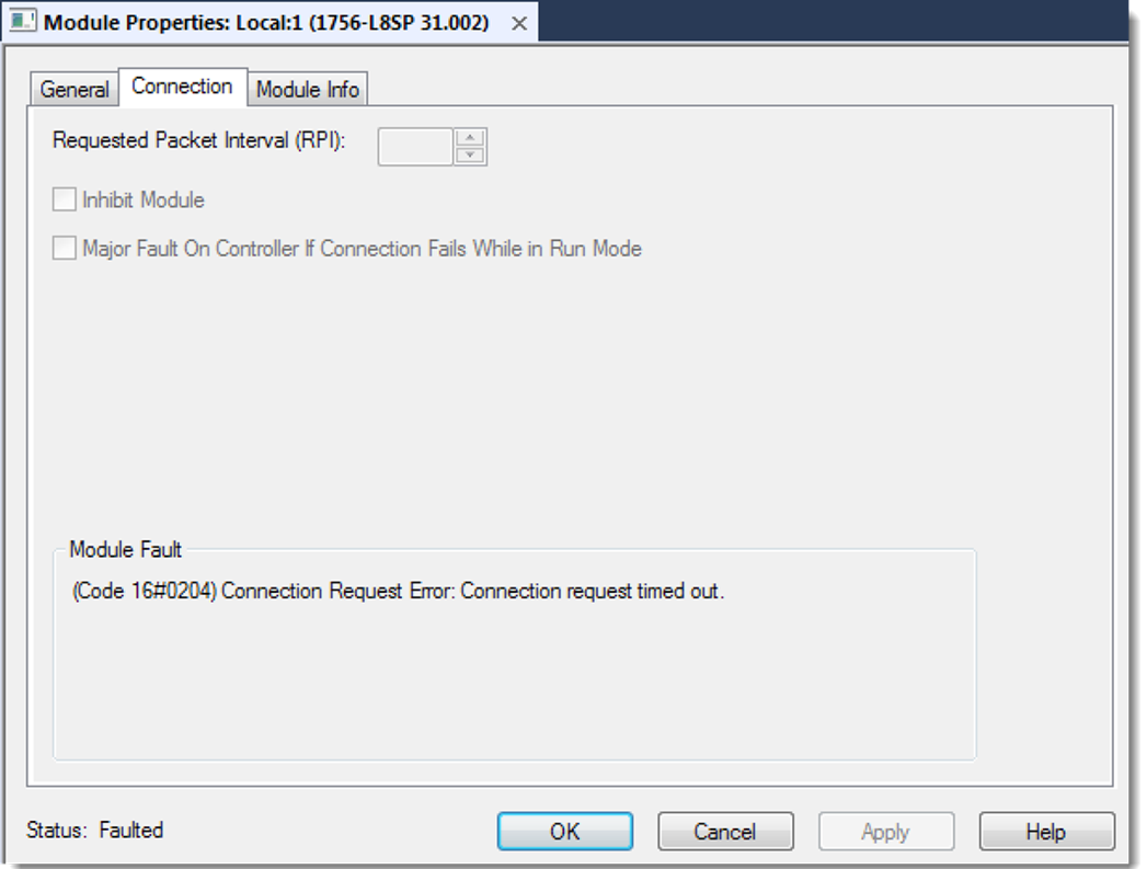
The status of the safety partner can be viewed on the Connection tab in the module properties.
Safety Partner Status
Safety Connection Status
For tags associated with consumed safety data, you can monitor the status of safety connections by using the CONNECTION_STATUS member. For monitoring input and output connections, safety I/O tags have a connection status member called SafetyStatus. Both data types contain 2 bits: ConnectionFaulted and RunMode.
The ConnectionFaulted value indicates whether the safety connection between the safety producer and the safety consumer is Valid (0) or Faulted (1). If ConnectionFaulted is set to Faulted (1) for any reason, the safety data is reset to zero and the RunMode value is set to Idle State (0).
The RunMode value indicates if consumed data is actively being updated by a device that is in the Run Mode (1) or Idle State (0). Idle state is indicated if the connection is closed, the safety task is faulted, or the remote controller or device is in Program mode or Test mode. For safety I/O connections, the RunMode is always inverse the ConnectionFaulted status. It does not provide unique data.
The following table describes the combinations of the ConnectionFaulted and RunMode states.
ConnectionFaulted Status | RunMode Status | Safety Connection Operation |
|---|---|---|
0 = Valid | 1 = Run | Data is actively being controlled by the producing device. The producing device is in Run mode. |
0 = Valid | 0 = Idle | The connection is active and the producing device is in the Idle state. The safety data is reset to zero. This applies to consumed connections only. |
1 = Faulted | 0 = Idle | The safety connection is faulted. The state of the producing device is unknown. The safety data is reset to zero and the RunMode value is set to Idle State (0). |
1 = Faulted | 1 = Run | Invalid state. |
If a device is inhibited, the ConnectionFaulted bit is set to Faulted (1) and the RunMode bit is set to Idle (0) for each connection associated with the device. As a result, safety consumed data is reset to zero.
ATTENTION:
Safety I/O connections and produced/consumed connections cannot be automatically configured to fault the controller if a connection is lost and the system transitions to the safe state. Therefore, if you must detect a device fault to be sure that the system maintains the required SIL level, you must monitor the safety I/O CONNECTION_STATUS bits and initiate the fault via program logic.
Safety I/O Status
Connection Status (.ConnectionFaulted) is the status of the safety connection between the safety controller and safety I/O module. When the connection is operating properly, this bit is LO (0). When the connection is not operating properly, this bit is HI (1). When the connection status is HI (connection not operating properly), all other module defined tags are LO and considered invalid data.
Point Status is available for both safety inputs (.PtxxInputStatus) and safety outputs (.PtxxOutputStatus). When a point status tag is HI (1), it indicates that individual channel is functioning and wired correctly, and that the safety connection between the safety controller and the safety I/O module on which this channel resides is operating properly.
Combined Status is also available for both safety inputs (.CombinedInputStatus) and safety outputs (.CombinedOutputStatus). When the combined status tag is HI (1), it indicates that all input or output channels on the module are functioning and wired correctly, and that the safety connection between the safety controller and the safety I/O module on which these channels reside is operating properly.
Whether combined status or point status is used is application-dependent. Point status simply provides more granular status.
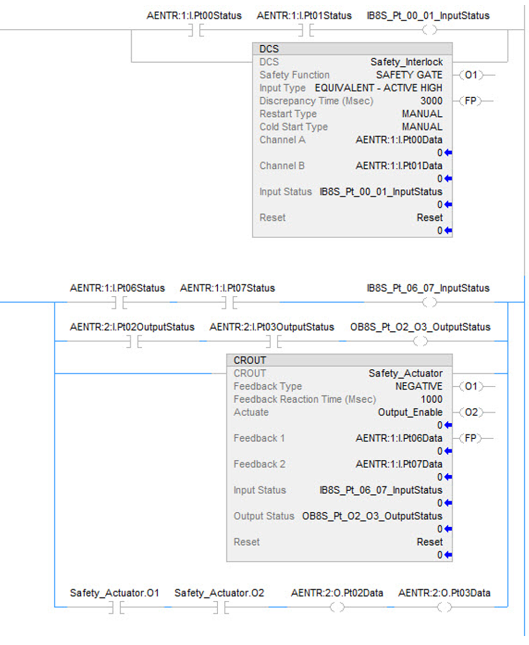
The dual-channel safety instructions have built in safety I/O status monitoring. Input status and Output status are parameters for the safety input and output instructions. The DCS instruction (and other dual-channel safety instructions) has input status for input channels A and B. The CROUT instruction has input status for Feedbacks 1 and 2, and has output status for the output channels that are driven by the CROUT outputs O1 and O2. The status tags used in these instructions must be HI (1) for the safety instruction output tags (O1 for input instructions and O1/O2 for CROUT) to be energized.
For proper safety instruction operation, it is important to drive the input status and output status tags BEFORE/ABOVE the safety instruction as shown in the following figure.
When you use instructions, such as XIC and OTE, you are responsible for interrogating the safety I/O status:
- Before you use a safety input channel as an interlock, verify that the safety input channel status is HI (1).
- Before you energize a safety output channel, verify that the safety output channel status is HI (1).
Instruction Examples
Provide Feedback