
Assign input and output variables to the user-defined function block
Use the steps to:
- Assign four Boolean input variables to the four L70E controller inputs.
- Assign output variables to the L70E controller outputs.
- Map the output variables in the function block to the L70E controller outputs.
After completing the task, the ladder diagram program can detect and control the following events:
When the North-South traffic light is red, or when the North or South sensor is tripped, the traffic light in the East-West direction changes to yellow after five seconds, and then to red in two more seconds.
Prerequisites
To assign input and output variables to a user-defined function block
- In the ladder editor, open the variable selector for each input variable, and then assign variables according to the following table.Assign variables to input variable boxesBoolean input variablesVariable nameN_CAR_SENSOR_IO_EM_DI_00S_CAR_SENSOR_IO_EM_DI_01E_CAR_SENSOR_IO_EM_DI_02W_CAR_SENSOR_IO_EM_DI_03TIP:
- To view the entire variable name and type, hover over the function block to show the tooltip.
- You can assign alias names to the variables.
- Assign the six L70E digital outputs according to the following table.Assign variables to digital outputsBoolean Output VariablesVariable NameNS_RED_LIGHTS_IO_EM_DO_00NS_YELLOW_LIGHTS_IO_EM_DO_01NS_GREEN_LIGHTS_IO_EM_DO_02EW_ RED_LIGHTS_IO_EM_DO_03EW_ YELLOW_LIGHTS_IO_EM_DO_04EW_ GREEN_LIGHTS_IO_EM_DO_05The first function block output that connects directly to the ladder rung is the function block output enabled (ENO) bit. It reflects the status of the input enable (EN) bit. The remaining six function block outputs are "real-world" outputs that connect to the red, yellow, and green traffic lights for each direction.When completed, the function block looks similar to the following image:
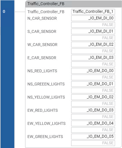
- (optional) Add the comments to the function block: This rung assigns theMicro870®I/O to the TRAFFIC_CONTROLLER function block.
- Build the project by doing one of the following:
- From the menu bar, select .
- Right-click the controller, and then selectBuild.
- InOutput, view the build result.
- (optional) Fix any errors, and then build the project again.
- Save the project by doing one of the following:
- From the menu bar, select
 .
. - From theFilemenu, selectSave.
Provide Feedback