Execution Order of FBD Programs
The execution order of a Function Block Diagram (FBD) diagram is the order in which the compiler executes the elements making up a program. Display the order of execution in the form of numerical tags for the following elements: coils, instances of function blocks, and variables where a value is assigned in the program. Perform this task from the menu bar, the toolbar, or using the keyboard shortcut (
Ctrl+W
).For the execution order of a program, a block is any object in the diagram, a network is a group of blocks linked together, and the position of a block is based on its top-left corner. For function blocks, the instance name is included in the bounding box and considered the top-left corner when defining the execution order Rules that apply to the execution order of the program are:
- Elements execute from top to bottom, then left to right.
- All inputs must be resolved or known, for an element in order to assign its outputs. A constant or unassigned variable is considered resolved. When the inputs of two or more elements are resolved at the same time, the decision for the execution is based on the position of the element (top to bottom, then left to right).
- The order of execution is assigned from 1 to n following the order in which the assignable elements are found.
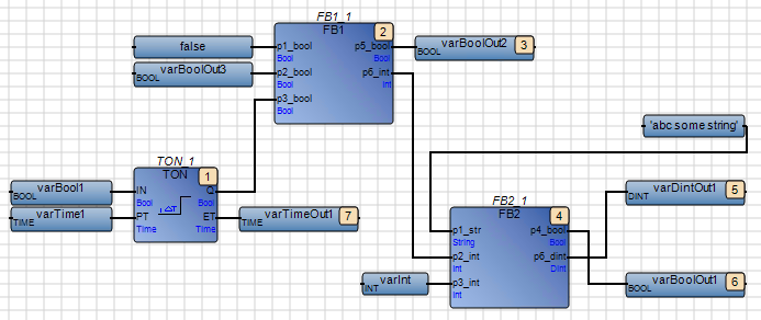
When analyzing the execution order for the following network, the compiler proceeds through the elements as indicated:
- The compiler immediately locates the topmost element FB1_1 in the diagram and notices that only the first two inputs of three inputs are resolved.
- To resolve the third input of element FB1_1, the compiler considers TON_1 where all inputs are resolved and assigns the first tag (1) for the execution order, since this block is the first to be resolved.
- Since resolving TON_1 enables resolving all inputs for FB1_1, the compiler assigns the next tag (2) to FB1_1.
- Because FB1_1 is resolved, the compiler starts assigning tags to the FB1_1 outputs which is not yet done for TON_1.
- Since varBoolOut2 is the top-leftmost of the FB1_1 outputs, the compiler assigns the third tag (3) and assigns the fourth tag (4) to the FB2_1 block.
- While FB1_1 is completely resolved, the compiler proceeds to resolving the FB2_1 outputs.
- The compiler assigns the fifth tag (5) to varDintOut1 since this output is the topmost of those to resolve, then the sixth tag (6) to varBoolOut1.
- The compiler assigns the next and final tag (7) to varTimeOut1.
To display the execution order in an FBD diagram
IMPORTANT:
After importing an
AADvance Workbench
version 1.1, 1.2, 1.3, or 1.4 project and opening a POU, check out the POU before displaying
the execution order.- From theFormatmenu, clickExecution Order.
Provide Feedback