Device Definition
This section shows definitions for specifc configurations chosen in the Device Definition
dialog.
To change the definition of a device, select Device definition in the Overview view.
Device Definition Overview
Use Overview view in the Device Definition dialog to define a device or change the
device definition.
Device Definition Overview Example
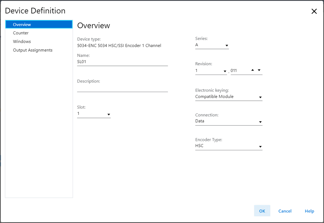
Overview includes these parameters:
Parameter | Definition | Available Choices |
|---|---|---|
Device Type | Displays the device catalog number and type. | Device-specific |
Name | Enter an IEC 61131 compliant device name. If an invalid character is entered in this field, or if the
name exceeds 40 characters, the software ignores the
character. | All valid values |
Description | Enter the description of the device. | All valid values |
Slot | Specify the slot number where the device resides. Only slots
between 1 and the maximum number of I/O devices are valid
depending on the platform. When the device is created, the slot number defaults to the
first available slot position. When the controller is changed to one supporting a smaller
maximum I/O count, the current slot value may no longer be
valid. | 1…32 |
Series | Specifies the series of the device. | Device-specific |
Revision | Specifies the major and minor revisions of the device. The
valid range for minor revision is from 1…255. | Device-specific |
Electronic Keying | Defines the electronic keying used for the device. Electronic
keying compares the device defined in the project to the
installed device. If keying fails, a fault occurs.
ATTENTION:
Be cautious when using Disable Keying. If used
incorrectly, this option can lead to personal injury
or death, property damage, or economic loss. We
strongly recommend that you do not use Disable
Keying. If you use Disable Keying, you must take
full responsibility for understanding whether the
device being used can fulfill the functional
requirements of the application. For detailed information on Electronic keying, see Electronic
Keying in Logix 5000 Control Systems Application Technique,
publication LOGIX-AT001. |
|
Connection | Specify the type of data transferred between the device and
controller. For the Listen Only choice, the controller and device
establish communication without the controller sending any
configuration or output data to the device. A full input
data connection is established but depends on the connection
between the owner-controller and the device. |
|
Encoder Type | Specify the type of encoder in which the module
operates. |
|
Define Counter
Use Define Counter to define the counter parameters when the Encoder Type is
configured as HSC.
Define Counter Example
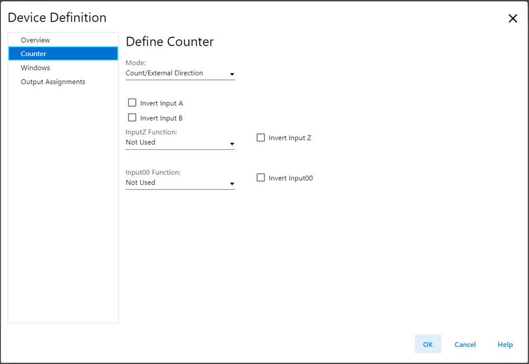
Define Counter includes these parameters:
Parameter | Definition | Available Choices |
|---|---|---|
Mode | Defines the mode in which the counter operates. |
|
Invert Input A | Determines whether to invert Input A. This parameter is only available when the counter mode is
configured as Count/External Direction, Count/Internal
Direction, or Up/Down Pulses. |
|
Invert Input B | Determines whether to invert Input B. This parameter is only available when the counter mode is
configured as Count/External Direction, Count/Internal
Direction, or Up/Down Pulses. |
|
Invert Input A, B | Determines whether to invert Input AB. This parameter is only available when the counter mode is
configured as Quadrature X1, Quadrature X2, or Quadrature
X4. |
|
Input Z Function | Defines the function for Input Z. Each counter function (Reset, Store, Load, Hold) can only be
triggered by one input. For example, if you select the Input Z Function as "Reset,
Hold", then the options that contain "Reset" and "Hold" are
not available to select for the Input00 Function. If you select any option for Input Z Function, then Input00
Function is automatically set to Not Used. |
|
Invert Input Z | Determines whether to invert Input Z. |
|
Input00 Function | Defines the function for Input00. Each counter function (Reset, Store, Load, Hold) can only be
triggered by one input. For example, if you select the Input Z Function as "Reset,
Hold", then the options that contain "Reset" and "Hold" are
not available to select for the Input00 Function. If you select any option for Input Z Function, then Input00
Function is automatically set to Not Used. |
|
Invert Input00 | Determines whether to invert Input00. |
|
Define Counter (Listen Only)
Use Define Counter to define the counter parameters when the Encoder Type is
configured as HSC and Connection is configured as Listen Only Data.
Define Counter (Listen Only) Example
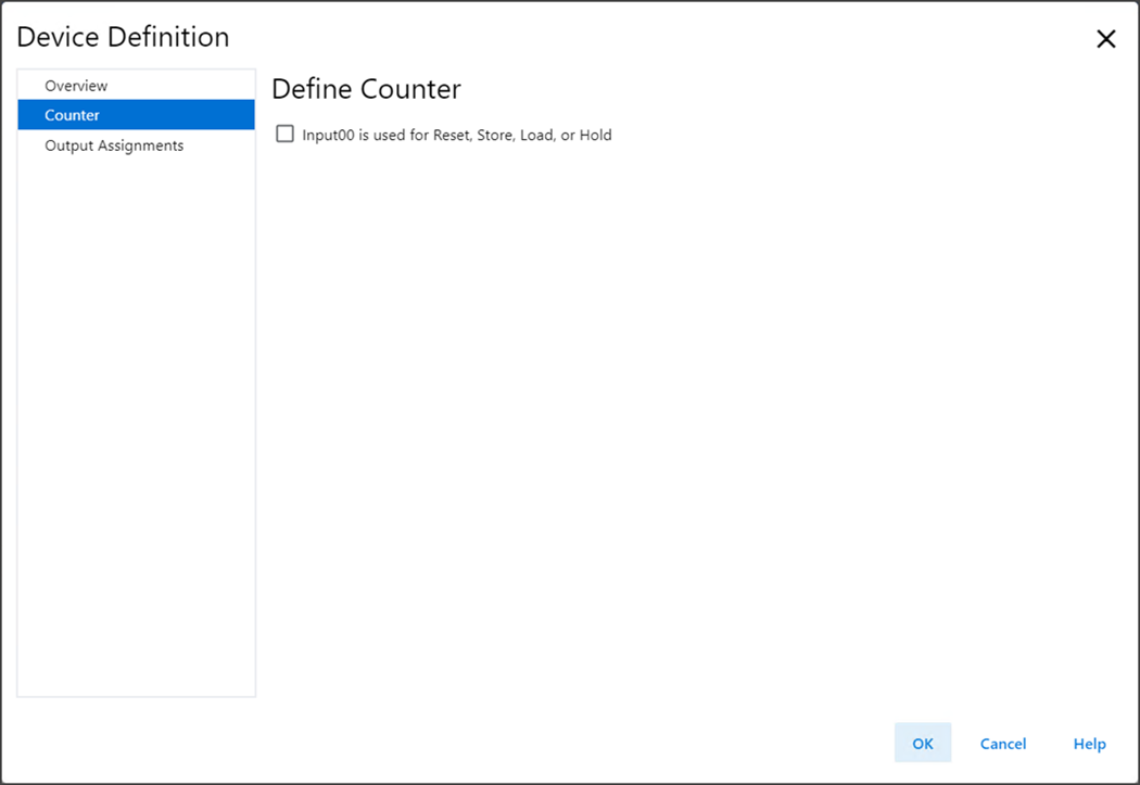
Define Counter (Listen Only) includes these parameters:
Parameter | Definition | Available Choices |
|---|---|---|
Input00 is used for Reset, Store, Load, or Hold | Determines whether to use Input00 to trigger counter
functions. |
|
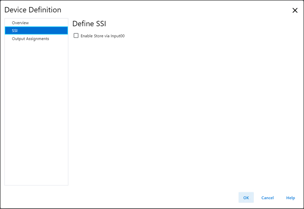
Define SSI
Use Define SSI to define the SSI parameters when the Encoder Type is configured as
SSI.
Define SSI Example
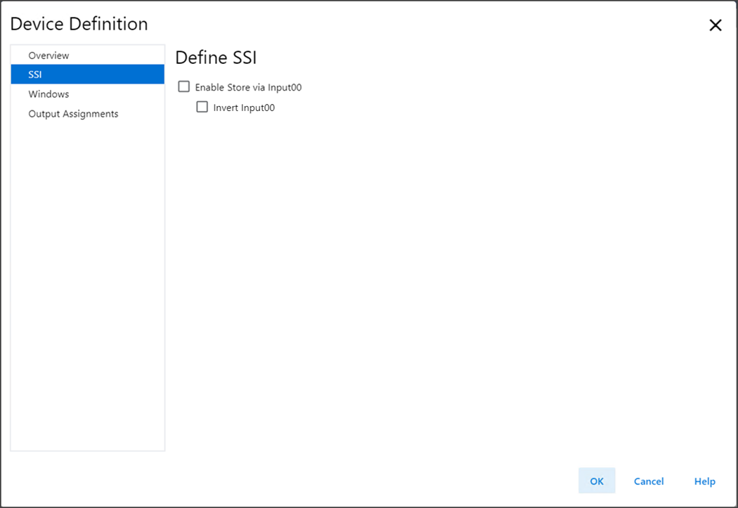
Define SSI includes these parameters:
Parameter | Definition | Available Choices |
|---|---|---|
Enable Store via Input00 | Defines whether the Store function is triggered using
Input00. |
|
Invert Input00 | Defines whether to invert the indicated input. |
|
Define SSI (Listen Only)
Use Define Counter to define the SSI parameters when the Encoder Type is configured
as SSI and Connection is configured as Listen Only Data.
Define SSI (Listen Only) Example
Define SSI (Listen Only) includes these parameters:
Parameter | Definition | Available Choices |
|---|---|---|
Enable Store via Input00 | Defines whether the Store function is triggered using
Input00. |
|
Define Windows
Use Define Windows to define the Windows parameters.
This view is not available when the Connection is configured as Listen Only Data.
Define Windows Example
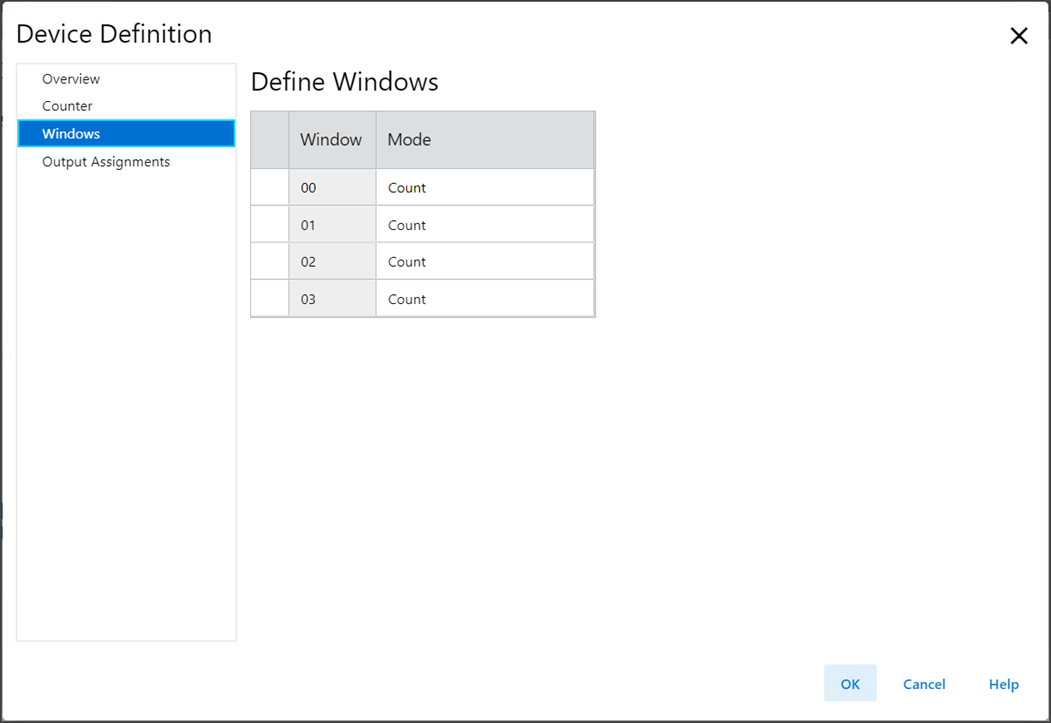
Define Windows includes these parameters:
Parameter | Definition | Available Choices |
|---|---|---|
Window | The window to which this configuration applies | 0…3 |
Mode | Defines the counter or SSI variable for the window to operate
on. | Options for HSC mode:
Options for SSI mode:
|
Define Output Assignments
Use Define Output Assignments to define the operating mode of the outputs.
Define Output Assignment Example
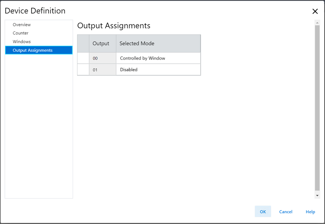
Define Output Assignments includes these parameters:
Parameter | Definition | Available Choices |
|---|---|---|
Output | The output to which this configuration applies. | 0…1 |
Selected Mode | Defines the mode in which the output operates. |
|
Provide Feedback