SCL instruction timing diagrams examples
The following timing diagram examples describe execution scenarios for the SCL (scaler with alarm) instruction.
Successful SCL execution
Successful SCL execution
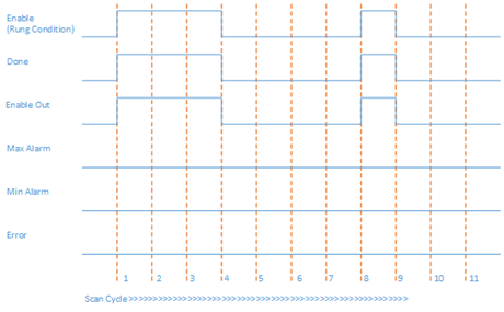
Scan Cycle | Description |
|---|---|
1 | When Enable is set to TRUE and input parameters are valid and within range, the Function Block execution starts.
|
2, 3 | No change in rung condition. |
4 | When Enable is set to FALSE, function block execution stops.
|
5, 6, 7 | No change in rung condition. |
8 |
|
9 | When Enable is set to FALSE, function block execution stops.
|
10, 11 | No change in rung condition. |
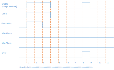
Failed SCL execution
Failed SCL execution
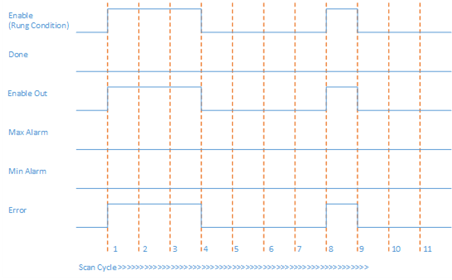
In this example, all the input parameters are valid and within range, but InRawMin >= InRawMax. In Scan Cycle 1 and 8, when Enable is set to TRUE and the function block execution starts, Error is set to True and ErrorID is set to 1.
Generation of MaxAlarm
Generation of MaxAlarm
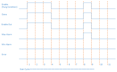
In Scan Cycle 8 of this example, all the input parameters are valid and within range, but In > InRawMax. When Enable is set to TRUE and the function block execution starts, MaxAlarm is set to TRUE.
Generation of MinAlarm
Generation of MinAlarm
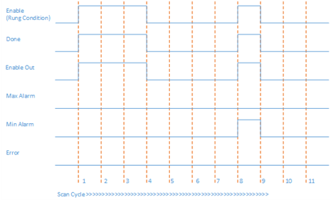
In Scan Cycle 8 of this example, all the input parameters are valid and within range, but In < InRawMin. When Enable is set to TRUE and the function block execution starts, MinAlarm is set to TRUE.
Output overflow condition and input configuration error
Output overflow condition and input configuration error
In Scan Cycle 3 of this example, function block input parameters are valid and within the range, but Out is overflowed because of input parameters. EnableOut is set to FALSE. Out value is invalid.
In Scan Cycle 8 of this example, function block input parameters are valid and within the range, but Out is overflowed because of input parameters and InRawMin >= InRawMax, Error is set to TRUE. ErrorID is set to 1 and Status is set to 3.
Provide Feedback