Example: How to create an IPIDController program to control water supply level
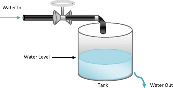
The water supply level control program example maintains sufficient water in a water supply tank that has an outflow. A solenoid valve controls incoming water and fills the tank at a preset rate; outflowing water is also controlled at a preset rate.
Example: How to create an IPIDController program to control water supply level
Program example information
The water supply level program example includes the following information:
- The sequence of events that occur in the control process.
- How the setpoint, process, and manipulated values are used in the control program.
- An example function block diagram that shows the IPIDController and other instruction blocks.
Setpoint, process and manipulated values
The following table defines how the SP, PV, and MV values are used in the water supply level program.
Item | Description |
|---|---|
Setpoint (SP) | Measurement of height that defines the target water supply level. |
Process value (PV) | The 4-20mA must be converted to the same unit as the SP, which is a measurement of height. |
Manipulated value (MV) | Must be converted to an analog value. So it can be output to the drive to control the pump. |
Water supply level system
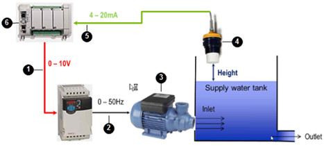
The following diagram shows the components in the water supply level system that are controlled by the water supply level program. The table following the diagram describes the events that occur when the control program runs.
Water supply level system
Sequence of events in water supply level system
The following table identifies the components in the water supply system and describes, in sequence, the events that occur in the system when the water supply level program runs.
No. | Item | Description |
|---|---|---|
 | Controller output | Sends the MV to the PowerFlex drive (0-10V). |
 | PowerFlex drive | Controls the water pump (0-50Hz). |
 | Water pump | Controls the water level in the supply tank. |
 | Output transfer device | Measures the height of the water supply level (4-20mA) and sends the PV to the controller. |
 | Controller input | Receives the PV (water supply level of 4-20mA). |
 | PLC program | Converts the PV to the same unit as the SP (measurement of height) and determines the difference between the PV and SP and adjusts the MV according to the parameter values defined in the P, I and D parameters. |
Example: Function block diagram to control water supply level
The following function block diagram shows the predefined and user-defined function blocks for the program to control the water supply level.
Function block diagram to control water supply level
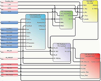
Function blocks and UDFBs used in the water level FBD
This application, developed in the FBD language, uses the instructions described in the following table.
Function Block | Description |
|---|---|
IPIDController function block | Provides PID process control. |
PID_OutputRegulator UDFB | Regulates the output of the IPIDCONTROLLER within a safe range to ensure the hardware used in the process is not damaged. Sample code:
|
PID_Feedback UDFB | Acts as a multiplexer. Sample code:
|
PID_PWM UDFB | Provides a PWM function, converting a real value to a time-related ON/OFF output. |
SIM_WATERLVL UDFB | Simulates the process in the application example. |
Provide Feedback