PID (proportional-integral-derivative)
PID is an output instruction that controls physical properties such as temperature, pressure, liquid level, and flow rate using process loops.
Operation details:
- When enabled, PID controls the process using the input parameters, including SP and Gains of the PID controller.
- Run to Program mode transition, the PID instruction is disabled, parameter values are retained.
- Program to Run mode transition, the PID instruction remains disabled until a user resets Enable to true.
Languages supported: Function block diagram, ladder diagram, structured text.
This instruction applies to the L20E, L50E, and L70E controllers.
PID
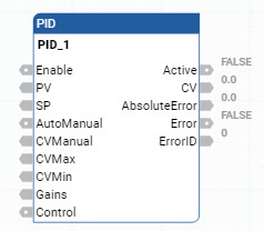
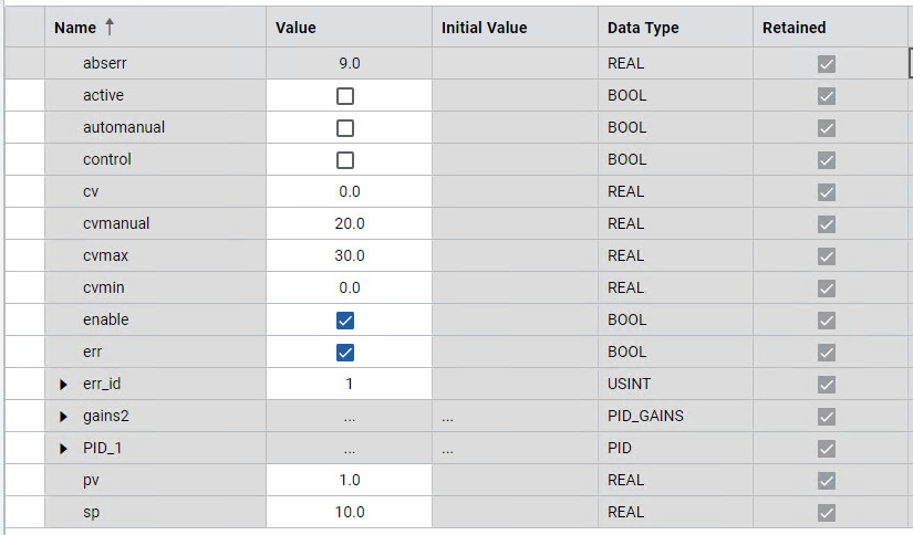
Parameter | Parameter Type | Data Type | Description |
|---|---|---|---|
Enable | Input | BOOL | Enable instruction.
|
PV | Input | REAL | Process Value. This value is typically read from an analog input module. The SI unit must be the same as Setpoint. |
SP | Input | REAL | The set point value for the process. |
AutoManual | Input | BOOL | Auto or manual mode selection.
|
CVManual | Input | REAL | Control value input defined for manual mode operation. The valid range for CVManual is: CVMin < CVManual < CVMax. |
CVMin | Input | REAL | Control value minimum limit.
|
CVMax | Input | REAL | Control value maximum limit.
|
Gains | Input | PID_GAINS | Gains of PID for controller. Use the PID_GAINS data type to configure the Gains parameter. |
Control | Input | BOOL | Control direction of the process:
|
Active | Output | BOOL | Status of the PID controller.
|
CV | Output | REAL | The control value output. If any error occurred, CV is 0. |
AbsoluteError | Output | REAL | Absolute error is the difference between process value (PV) and set point (SP) value. |
Error | Output | BOOL | Indicates the existence of an error condition.
|
ErrorID | Output | USINT | A unique numeric that identifies the error. The errors are defined in PID error codes. |
Parameter | Parameter Type | Data Type | Description |
|---|---|---|---|
Kc | Input | REAL | Controller gain for PID. Proportional and Integral are dependent on this gain. (>= 0.0001). Increasing Kc improves response time but also increases overshoot and oscillation of the PID. If Kc is invalid, an error occurs. |
Ti | Input | REAL | Time integral constant in seconds (>= 0.0001). Increasing Ti decreases the overshoot and oscillation of the PID. If Ti is invalid, an error occurs. |
Td | Input | REAL | Time derivative constant in seconds (>= 0.0). When Td equals 0, there is no derivative action and PID becomes a PI controller. Increasing Td reduces the overshot and removes the oscillation of the PID controller. If Td is invalid, an error occurs. |
FC | Input | REAL | Filter constant (>= 0.0). Recommended range for FC is from 0 through 20. Increasing FC smooths the response of the PID controller. If FC is not valid, an error occurs. |
Error Code | Error Description |
|---|---|
0 | PID is working normally. |
1 | Kc is not valid. |
2 | Ti is not valid. |
3 | Td is not valid. |
4 | FC is not valid. |
5 | CVMin > CVMax or CVMax < CVMin. |
6 | CVManual < CVMin. CVManual is invalid. |
7 | CVManual > CVMax. CVManual is invalid. |
PID examples
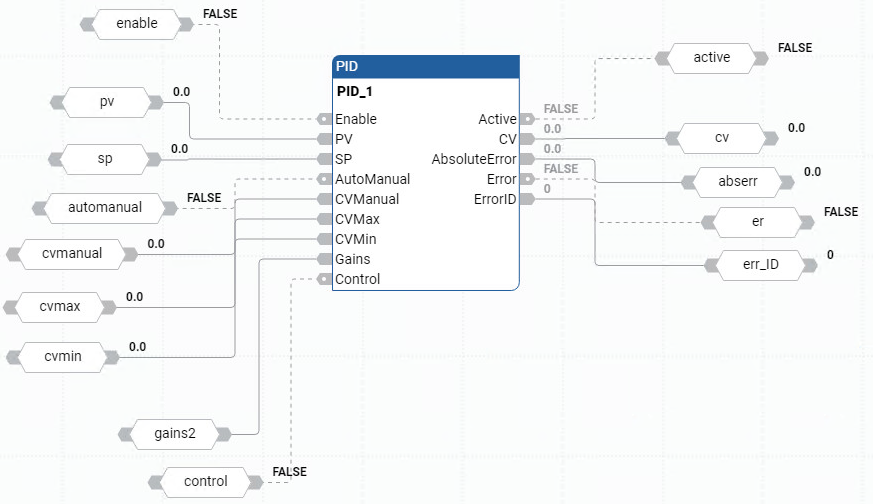
PID function block diagram example
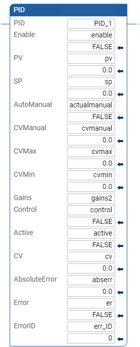
PID ladder diagram example
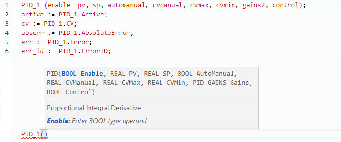
PID structured text example
Results
Provide Feedback