IPIDCONTROLLER (proportional-integral-derivative controller)
Configure and control the inputs and outputs used for proportional-integral-derivative (PID) logic. PID logic is used to control physical properties such as temperature, pressure, liquid, level, or flow rate by using process loops that calculate an error value as the difference between a desired setpoint and a measured process variable. The controller attempts to minimize the error over time by the adjustment of a control variable. The calculation includes proportional (P), integral (I), and derivative(D) terms, which are used as follows:
- P: Present values of the error.
- I: Past values of the error.
- D: Possible future values of the error, based on its current rate of change. which controls physical properties such as temperature, pressure, liquid level, or flow rate using process loops.
Languages supported: Function block diagram, ladder diagram, structured text.
This instruction applies to the Micro810, L20E, L50E, and L70E controllers.
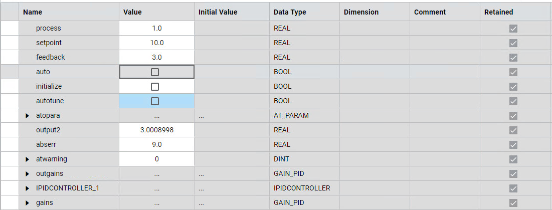
IPIDCONTROLLER
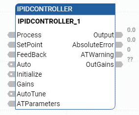
Parameter | Parameter Type | Data Type | Description |
|---|---|---|---|
EN | Input | BOOL | When TRUE, enables the instruction block.
Applies to ladder diagram programs. |
Process | Input | REAL | Process value, which is the value measured from the process output. |
SetPoint | Input | REAL | Set point. |
FeedBack | Input | REAL | Feedback signal, which is the value of the control variable applied to the process. For example, the feedback can be IPIDCONTROLLER output. |
Auto | Input | BOOL | The operation mode of the PID controller:
|
Initialize | Input | BOOL | A change in value (TRUE to FALSE or FALSE to TRUE) causes the controller to eliminate any proportional gain during that cycle. Also initializes AutoTune sequences. |
Gains | Input | GAIN_PID | Gains PID for IPIDController. Use the GAIN_PID data type to define the parameters for the Gains input. |
AutoTune | Input | BOOL |
|
ATParameters | Input | AT_Param | Auto Tune Parameters. Use the AT_Param data type to define the parameters for the ATParameters input. |
Output | Output | REAL | Output value from the controller. |
AbsoluteError | Output | REAL | Absolute error (Process – SetPoint) from the controller. |
ATWarnings | Output | DINT | (ATWarning) Warning for the Auto Tune sequence. Possible values are:
|
OutGains | Output | GAIN_PID | Gains calculated after AutoTune sequences. Use the GAIN_PID data type to define the OutGains output. |
ENO | Output | BOOL | Enable output. Applies to ladder diagram programs. |
IPIDCONTROLLER examples
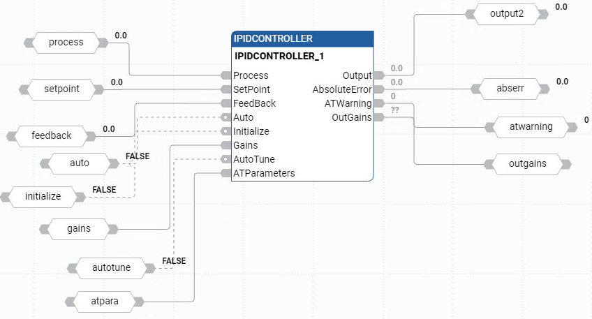
IPIDCONTROLLER function block diagram example
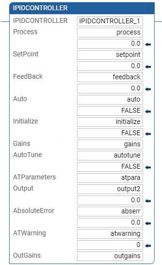
IPIDCONTROLLER ladder diagram example
IPIDCONTROLLER structured text example
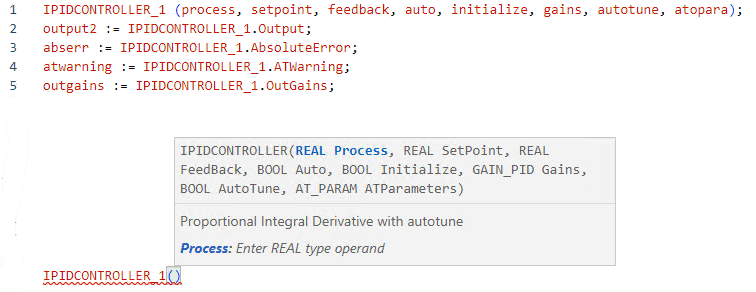
(* ST equivalence: IPIDController1 is an instance of IPIDController block *)


IPIDController1(Proc,

SP,
FBK,
Auto,
Init,
G_In,
A_Tune,
A_TunePar,
Err );
Out_process := IPIDController1.Output ;

A_Tune_Warn := IPIDController1.ATWarning ;

Gain_Out := IPIDController1.OutGains ;
Results
Provide Feedback