Fiber Channel Operation
The dual SFP ports on the redundancy module operate as a redundant communication channels between partner redundancy modules. On 1756-RM3 modules, communication occurs on both channels. If one channel fails, communication persists on the other channel with no delay. Channel switchovers do not occur on 1756-RM3 modules.
IMPORTANT:
When you connect the fiber channels between partner redundancy modules, connect matching ports. For example, connect Link 1 on the primary module to Link 1 on the secondary module.
The use of both fiber channels is not required, but recommended for redundancy.
Causes of a Fiber Channel Failure
Any of the following can cause a loss of operation between fiber channels:
- Signal attenuation along the fiber cable path that is routed between the partner redundancy modules
- A broken or damaged fiber cable that is routed between the partner redundancy modules
- Improper or loosely fit cable connector
- SFP transceiver fault
- Removal or loose connection of the SFP transceiver
- Data communication error that is signaled by a failed CRC check
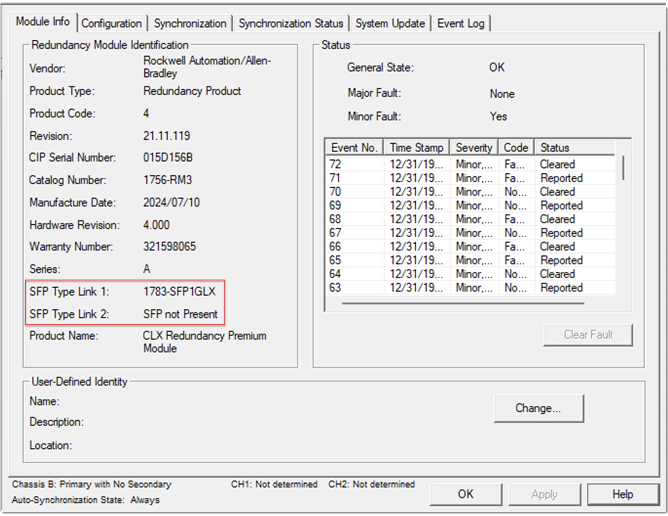
Identify Installed SFP Transceivers
You can identify the SFP transceivers that are installed in the dual SFP ports from the Module Info tab in the
FactoryTalk® Linx
Redundancy Module Configuration Tool (RMCT). The SFP Type Link 1 and SFP Type Link 2 fields display one of the following values:- SFP Not Present
- SFP Not Supported
- 1783-SFP1GSX
- 1783-SFP1GLX
- 1783-SFP1GEXE
- 1783-SFP1GZX
For SFP transceiver technical specifications, see the ControlLogix and GuardLogix Controller Specifications Technical Data, publication 1756-TD001.
SFP Transceiver Identification
Provide Feedback