
Motor Brake
The axis supports an external brake control that can be controlled using the
I.Axisxx.BrakeReleased tag.
The following example shows an output point (Pt00) of the 5034-OB16 module in slot 5 is
used as the external brake control with normally closed. The 5034-STEPD module is in
slot 2.
External Brake Control Ladder Diagram Example – Normal Operation

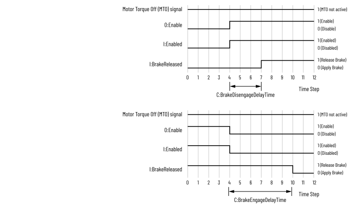
Brake is released when the axis is enabled (powered on). Brake is applied when the axis is
disabled (powered off) or when the axis is de-energized due to a fault.
Use C.Axisxx.BrakeEngageDelayTime to configure the time from when the axis is disabled
until the brake is applied. Use C.Axisxx.BrakeDisengageDelayTime to configure the time
from Hold current is applied until the brake is released.
Motor Brake Timing Diagram
WARNING:
Applying brake immediately when the axis is
moving fast and there is too much inertia can cause the brake to shatter. You must
configure proper delays for safe operation.
IMPORTANT:
To help avoid the scenario where the brake
control is active but the axis is not, the stepper module and the output point that
is controlling the motor brake should be:
- In the same backplane
- Both have an RPI less than 50 ms
External Brake Faulted
If the stepper module connection to the controller is good but the
output point that is configured as an external brake control is faulted, the ladder
must check the fault bit of the output point and notify the stepper module by
setting the O.Axisxx.BrakeFaulted tag. When O.Axisxx.BrakeFaulted is set to 1, the
axis performs a hard stop.
You must configure the output point's behavior during Communication Fault Mode
state:
- If C.Axisxx.BrakeEngageDelayTime is 0, Communication Fault Mode = Off
- If C.Axisxx.BrakeEngageDelayTime is greater than 0:
- Communication Fault Mode = Hold
- Communication Fault Mode Output State Durartion = 1 s
- Communication Fault Mode Final Output State = Off
The following example shows an output point (Pt00) of the 5034-OB16 module in slot 5
is used as the external brake control. The 5034-STEPD module is in slot 2.
External Brake Control Ladder Diagram Example – Brake Fault

IMPORTANT:
You must configure the ladder program
with the output point's Final Output State During Communication Fault Mode to be
Off.
The I.Axisxx.BrakeReleased tag continues to function normally even when
O.Axisxx.BrakeFaulted is set.
Provide Feedback