
General Precautions
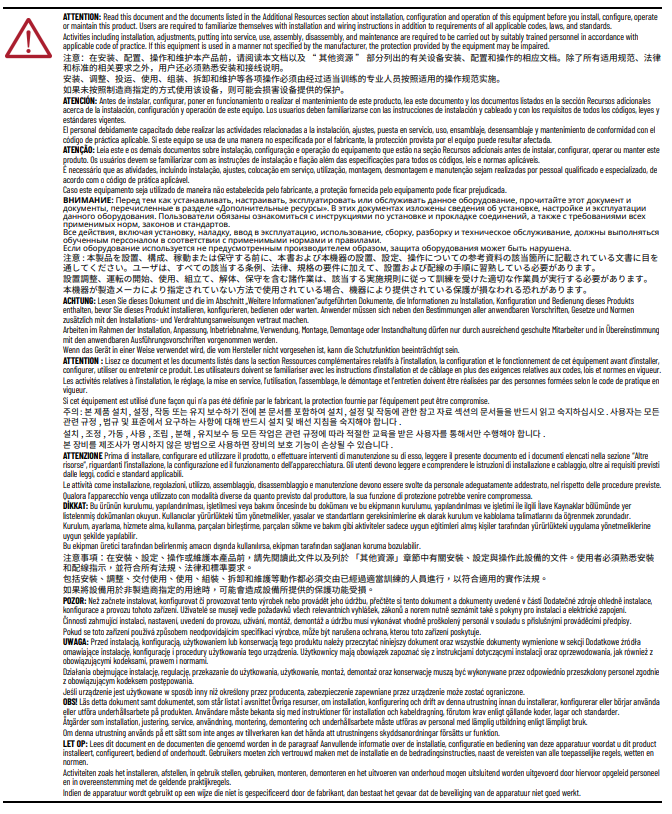
ATTENTION:
Environment and Enclosure
This equipment is intended for use in a Pollution Degree 2 industrial environment, in overvoltage Category II applications (as defined in EN/IEC 60664-1), at altitudes up to 2000 m (6562 ft) without derating. This equipment is not intended for use in residential environments and may not provide adequate protection to radio communication services in such environments. This equipment is designated and supplied as open-type equipment for indoor use. It must be mounted within an enclosure that is suitably designed for those specific environmental conditions that are present and appropriately designed to help prevent personal injury resulting from accessibility to live parts. The enclosure must have suitable flame-retardant properties to prevent or minimize the spread of flame, complying with a flame spread rating of 5VA or be approved for the application if nonmetallic. The interior of the enclosure must be accessible only by the use of a tool. Subsequent sections of this publication may contain more information regarding specific enclosure type ratings that are required to comply with certain product safety certifications. In addition to this publication, see the following:
- Industrial Automation Wiring and Grounding Guidelines, publication 1770-4.1, for more installation requirements.
- NEMA Standard 250 and EN/IEC 60529, as applicable, for explanations of the degrees of protection provided by enclosures.
ATTENTION:
Prevent Electrostatic Discharge
This equipment is sensitive to electrostatic discharge, which can cause internal damage and affect normal operation. Follow these guidelines when you handle this equipment:
- Touch a grounded object to discharge potential static.
- Wear an approved grounding wriststrap.
- Do not touch connectors or pins on component boards.
- Do not touch circuit components inside the equipment.
- Use a static-safe workstation, if available.
- Store the equipment in appropriate static-safe packaging when not in use.
ATTENTION:
This product is grounded through the DIN rail to chassis ground. Use zinc-plated chromate-passivated steel DIN rail to assure proper grounding. The use of other DIN rail materials (for example, aluminum or plastic) that can corrode, oxidize, or are poor conductors, can result in improper or intermittent grounding. Secure DIN rail to mounting surface approximately every 200 mm (7.8 in.) and use end-anchors appropriately. Be sure to ground the DIN rail properly. See the Industrial Automation Wiring and Grounding Guidelines, Rockwell Automation publication 1770-4.1, for more information.
Electrical Safety Considerations
ATTENTION:
Power to this equipment and all connected I/O must be supplied from a source
compliant with the following:
- SELV source approved to EN/IEC60950-1, EN/IEC61010-2-201 or EN/IEC62368-1 (ES1)
- PELV source approved to EN/IEC60950-1, EN/IEC61010-2-201 or EN/IEC62368-1 (ES1)
- All wiring must comply with applicable electrical installation requirements [N.E.C. article 501-4(b)].
- Wire conductor and insulation ratings shall support minimum temperature rating of 105 °C (221 °F).
- Do not wire more than 2 conductors on any terminal.
- In case of malfunction or damage, no attempts at repair should be made. The module should be returned to the manufacturer for repair. Do not dismantle the module.
- This equipment is certified for use only within the surrounding air temperature range of -25…+60 °C (-13…+140 °F) for horizontal orientation and -25…+55 °C (-13…+131 °F) for other orientations. The equipment must not be used outside of this range.
- Use only a soft dry anti-static cloth to wipe down equipment. Do not use any cleaning agents.
ATTENTION:
Do not discard the end cap. Use this end cap to cover the exposed interconnections on the
adapter or the last mounting base on the DIN rail. Failure to do so could result in
equipment damage or injury from electric shock.
UK and European Hazardous Location Approval
The following applies to products marked II 3 G:
|
IEC Hazardous Location Approval
The following applies to products with IECEx certification:
|
WARNING:
Special Conditions for Safe Use:
- This equipment is not resistant to sunlight or other sources of UV radiation.
- This equipment shall be mounted in an UKEX/ATEX/IECEx Zone 2 certified enclosure with a minimum ingress protection rating of at least IP54 (in accordance with EN/IEC 60079-0) and used in an environment of not more than Pollution Degree 2 (as defined in EN/IEC 60664-1) when applied in Zone 2 environments. The enclosure must be accessible only by the use of a tool.
- This equipment shall be used within its specified ratings defined by Rockwell Automation.
- Transient protection shall be provided that is set at a level not exceeding 140% of the peak-rated voltage at the supply terminals to the equipment.
- The instructions in the user manual shall be observed.
- This equipment must be used only with UKEX/ATEX/IECEx certified Rockwell Automation backplanes.
- Secure any external connections that mate to this equipment by using screws, sliding latches, threaded connectors, or other means provided with this product.
- Do not disconnect equipment unless power has been removed or the area is known to be nonhazardous.
- Earthing is accomplished through mounting of modules on the DIN rail.
- The installer shall ensure that the service temperature of the suitably certified enclosure and the “maximum ambient” temperature of the module when installed is not exceeded.
WARNING:
When you insert or remove the module while backplane power is on, an electric arc can occur. This could cause an explosion in hazardous location installations.
Be sure that power is removed or the area is nonhazardous before proceeding. Repeated electric arcing causes excessive wear to contacts on both the module and its mating connector. Worn contacts may create electrical resistance that can affect module operation.
WARNING:
If you connect or disconnect the removable terminal block (RTB) with power applied, an electric arc can occur. This could cause an explosion in hazardous location installations.
Do not connect or disconnect the RTB while power is applied. Be sure that power is removed before proceeding.
WARNING:
If you connect or disconnect the communications cable with power applied to this module or any device on the network, an electric arc can occur. This could cause an explosion in hazardous location installations.
Be sure that power is removed or the area is nonhazardous before proceeding.
WARNING:
If you connect or disconnect wiring while the field-side power is on, an electric arc can occur. This could cause an explosion in hazardous location installations. Be sure that power is removed or the area is nonhazardous before proceeding.
North American Hazardous Location Approval
The following information applies when operating this equipment in hazardous locations. | Informations sur l’utilisation de cet équipement en environnements dangereux. |
|---|---|
Products marked "CL I, DIV 2, GP A, B, C, D" are suitable for use in Class I Division 2 Groups A, B, C, D, Hazardous Locations and nonhazardous locations only. Each product is supplied with markings on the rating nameplate indicating the hazardous location temperature code. When combining products within a system, the most adverse temperature code (lowest "T" number) may be used to help determine the overall temperature code of the system. Combinations of equipment in your system are subject to investigation by the local Authority Having Jurisdiction at the time of installation.
WARNING:
Explosion Hazard
| Les produits marqués "CL I, DIV 2, GP A, B, C, D" ne conviennent qu'à une utilisation en environnements de Classe I Division 2 Groupes A, B, C, D dangereux et non dangereux. Chaque produit est livré avec des marquages sur sa plaque d'identification qui indiquent le code de température pour les environnements dangereux. Lorsque plusieurs produits sont combinés dans un système, le code de température le plus défavorable (code de température le plus faible) peut être utilisé pour déterminer le code de température global du système. Les combinaisons d'équipements dans le système sont sujettes à inspection par les autorités locales qualifiées au moment de l'installation.
WARNING:
Risque d’Explosion
|
For 5034-AENTR and 5034-AENTRXT
ATTENTION:
US FCC Approval
This device complies with part 15 of the FCC Rules
Operation is subject to the following two conditions:
- This device may not cause harmful interference.
- This device must accept any interference received, including interference that may cause undesired operation.
Changes or modifications not expressly approved by manufacturer could void the user’s
authority to operate the equipment.
This equipment has been tested and found to comply with the limits for a Class A
digital device, pursuant to part 15 of the FCC Rules.
These limits are designed to provide reasonable protection against harmful interference
when the equipment is operated in a commercial environment.
This equipment generates, uses, and can radiate radio frequency energy and, if not
installed and used in accordance with the instruction manual, may cause harmful
interference to radio communications.
Operation of this equipment in a residential area is likely to cause harmful
interference in which case the user will be required to correct the interference at his
own expense.
ATTENTION:
微功率短距离设备声明:
使用微功率短距离无线电发射设备应当符合国家无线电管理有关规定。
- 符合“微功率短距离无线电发射设备目录和技术要求”中通用微功率设备 C 类设备技术要求,用于数据通信应用。采用内置天线。控制、开关等信息等请参考PointMax™ EtherNet/IP™ Adapter 使用手册。
- 不得擅自改变使用场景或使用条件、扩大发射频率范围、加大发射功率(包括额外加装射频功率放大器),不得擅自更改发射天线;
- 不得对其他合法的无线电台(站)产生有害干扰,也不得提出免受有害干扰保护;
- 应当承受辐射射频能量的工业、科学及医疗(ISM)应用设备的干扰或其他合法的无线电台(站)干扰;
- 如对其他合法的无线电台(站)产生有害干扰时,应立即停止使用,并采取措施消除干扰后方可继续使用;
- 在航空器内和依据法律法规、国家有关规定、标准划设的射电天文台、气象雷达站、卫星地球站(含测控、测距、接收、导航站)等军民用无线电台(站)、机场等的电磁环境保护区域内使用微功率设备,应当遵守电磁环境保护及相关行业主管部门的规定;
- 禁止在以机场跑道中心点为圆心,半径5000米的区域内使用各类模型遥控器
- 微功率设备使用时温度和电压的环境条件与PointMax™ EtherNet/IP™ Adapter 相同。
For 5034-OW4I and 5034-OW4IXT
ATTENTION:
- When using 240V power to a relay, you must connect a snubber across the load. Failure to connect a snubber across the load (relay contacts) can result in generation of electromagnetic noise, which could disrupt nearby electrical equipment, including your PointMax I/O system. Use Allen-Bradley® part number 599-KA04 or 1401-NX1.
- When hazardous voltage is present, before removing the RTB or inserting/removing any wires from the RTB, verify the following:
- Power to the RTB is removed.
- No wires are exposed on the RTB.
For 5034-IA8, 5034-IA8XT, 5034-OA4, and 5034-OA4XT
ATTENTION:
- Before performing Removal and Insertion Under Power (RIUP) on the I/O module, verify that LA power to the module is turned off.
- Before inserting or removing any wires from the removable terminal block (RTB), verify that:
- LA power is turned off.
- No wires are exposed on the RTB.
- When hazardous voltage 110…240V is present, activities including instalation, adjustments, putting into service, use, assembly, disassembly, and maintenance are required to be carried out by suitably trained personnel in accordance with applicable code of practice.
For 5034-STEPD and 5034-STEPDXT
When wiring the 5034-STEPD and 5034-STEPDXT modules, follow these guidelines:
|
Provide Feedback