Downloads

Kinetix Primer Integration

What is this for?
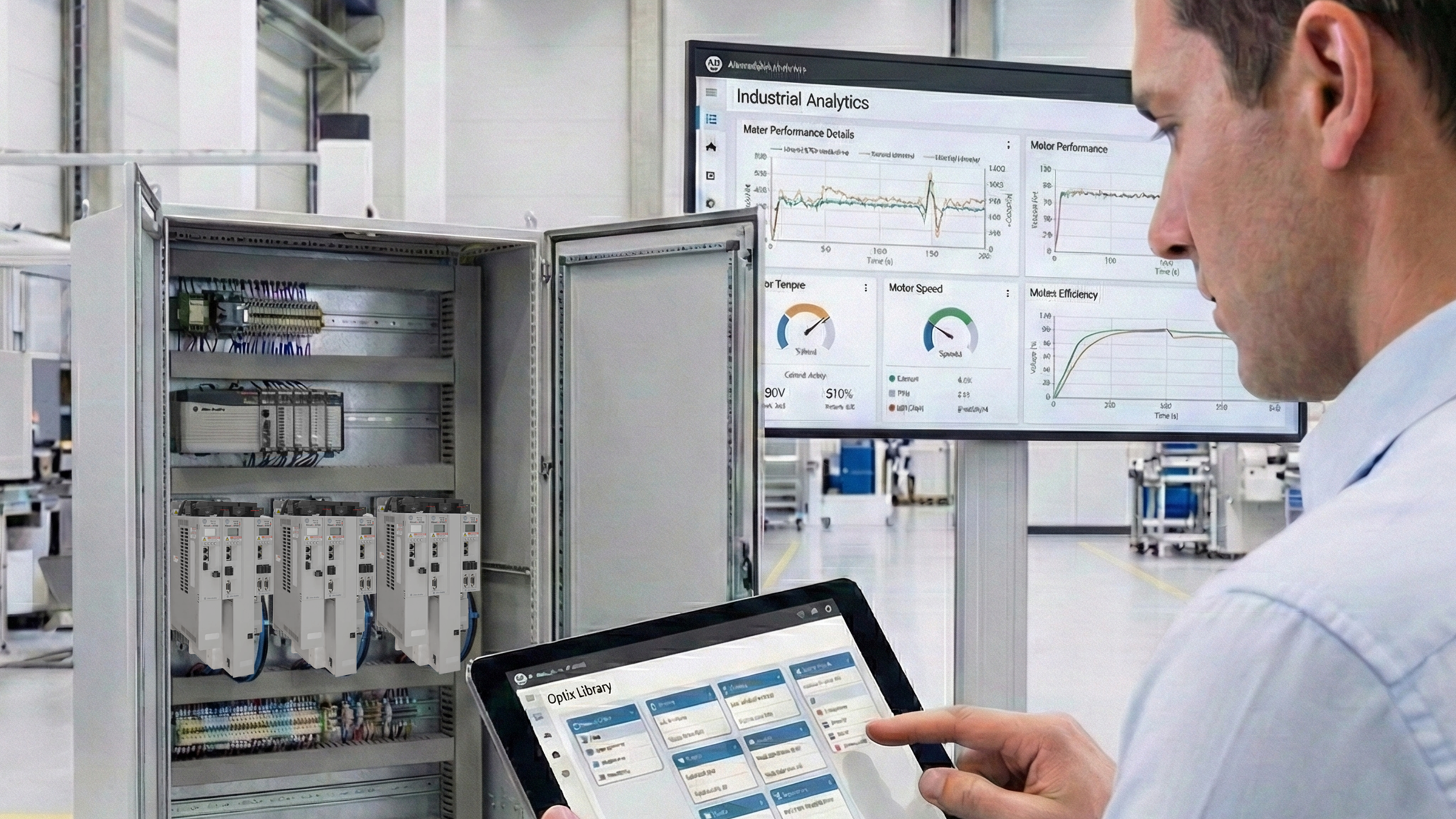
Premier integration from Rockwell Automation enhances motion control by enabling Kinetix drives and Logix controllers to work natively within an integrated design environment. Using a single software to configure both simplifies axis programming, synchronization, and motion profile management, while configurations are automatically stored in the controller.
This integration provides advanced diagnostics for predictive maintenance, improved visualization through pre-engineered graphics, and automatic device configuration, reducing downtime by restoring firmware and parameters after replacements. The result: an optimized motion solution that boosts efficiency, reliability, and customer productivity.
Is this useful to me?
This is useful because Premier Integration between Kinetix drives and Logix controllers delivers key benefits for motion control applications:
- Simplified design and programming: A single software to configure controllers and drives reduces time and errors.
- Precise synchronization and profile management: Ideal for multi-axis systems and complex applications.
- Advanced diagnostics and predictive maintenance: Detect issues before failures occur, preventing unplanned downtime.
- Enhanced visualization: Pre-engineered graphics make operation and monitoring easier.
- Automatic device configuration: Minimizes downtime when replacing drives by restoring firmware and parameters without manual intervention.
Application areas - Food, Manufacturing, Beverage

Please note: You will need to agree to the Terms & Conditions for each download.

Need Help?
If you need help with an application or have feedback from the Innovation Center, please contact us.
How can I make it work?
- Hardware
- Personal computer
- Software
- FactoryTalk Optix
- Studio 5000
- FT Echo
- Background knowledge
- Knowledge of programming and configuration in FT Optix and Studio 5000.

Implementation Guide
This document is divided into two parts, two configurations are needed. One for FT Optix and the Studio 5000 configuration.
First we will configure Studio 5000.
Part I.
Use Rockwell Automation Device Libraries in Studio 5000 Logix Designer
Prerequisites
- Basic knowledge of Studio 5000 Logix Designer.
- An existing project already created.
- (Recommended) Studio 5000 Application Code Manager (ACM) installed to speed up the configuration process.
- Step 1.1
- Step 1.2
- Step 1.3
- Step 1.4
- Step 1.5
- Step 1.6
Step 1.1
1. Download the Device Libraries
- Go to the Rockwell Automation Download Center: rockwellautomation.com.
- Search for “Device Library” and download the required libraries.
- (Optional) Download Studio 5000 Application Code Manager (ACM) if you haven’t already.
- This free software simplifies and accelerates device library configuration.
- It acts as an extension of Logix Designer for bulk project configuration.
Step 1.2
2. Register the Library in Application Code Manager (ACM)
- Locate the setup command file in the root folder of the library.
- Run the script to automatically register all library objects in ACM.
- Once the script is completed, close the window.
Step 1.3
3. Import Library Objects Using the Import Library Objects Plugin
In your Logix Designer project, right-click on any Task.
Select Plugins → Import Library Objects.
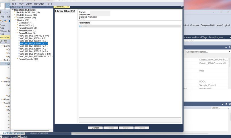
The Library Object Import Wizard will open this is a lightweight version of ACM inside Logix Designer.
On the left panel, you’ll see your list of registered libraries (those for which you ran the setup script).
Inside ralib device folder, you’ll find all Rockwell Automation device library objects.
Common folders include power discrete devices, network devices, etc.
For example, open the Power Motion folder and drag Kinetix 5500 device into the right panel under Library Objects.
You can drag multiple devices or instances if you wish to configure them in one import process.
kinetix-primer-integration_Imagen 1
Step 1.4
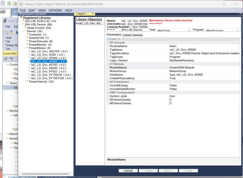
4. Configure Object Parameters
In the Object Configuration window, fill out the object parameters:
- Name → The instance name for the AOI.
- Description → A short helpful text that appears in the AOI description field and HMI faceplates.
Use the dropdowns to select the Task and Program where the routine will be imported.
Under Tag Scope, choose whether to create Program Scope or Controller Scope tags.
For some power device objects, configure Object Interface Data Type:
If using a PlantPAx system with a P controller, select Predefined Data Type and Controller Scope tags.
Set Include Hardware as needed:
- True → The wizard automatically creates and configures the device module in the IO Tree.
- False → If you already have the module, make sure it matches the required definition in the Device Library Reference Manual.
Verify the generated Module Name do not use the same name as the AOI.
kinetix-primer-integration_Imagen 2
Step 1.5
5. Complete the Import Wizard
In the Linked Libraries tab, click Auto Create to generate all required components.
Click Next to review pending changes.
Unless specific modifications are required, proceed to Finish.
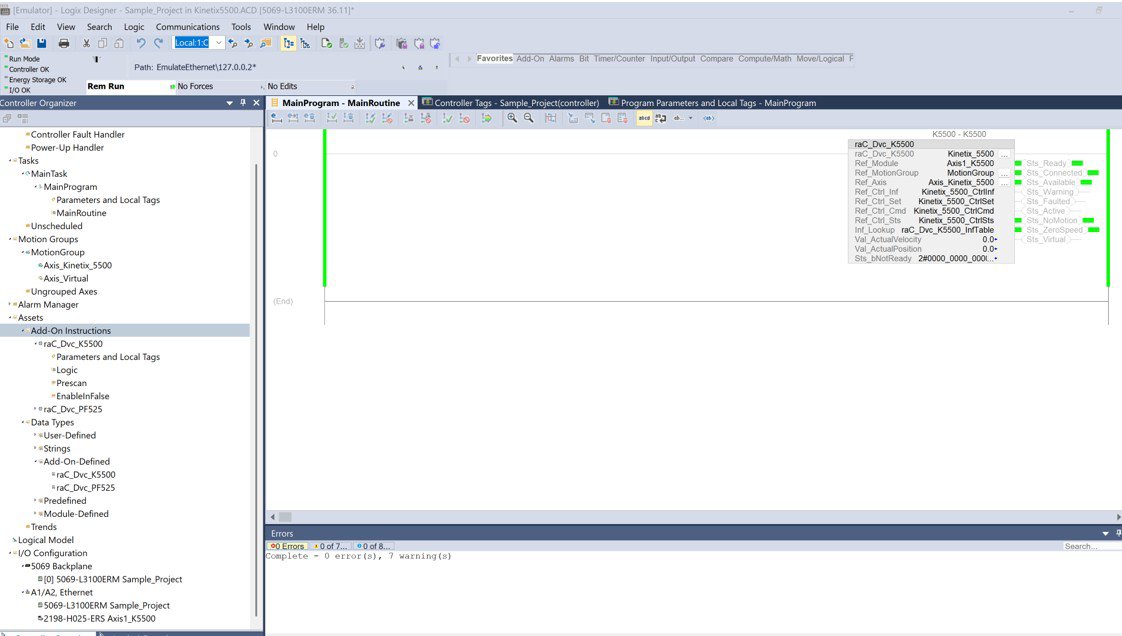
Once the import completes: The module appears in the IO Configuration Tree.
A new routine is created with a rung containing the AOI instance and all required tags.
The code should compile without errors — no manual programming needed.
kinetix-primer-integration_Imagen 3
Step 1.6
6. Integrate Custom Logic
Device AOIs include interface tags used to connect your own control logic:
- CMD (Command) → Used to control device outputs (e.g., Start, Jog, Locate LED).
- STS (Status) → Provides status feedback (faults, warnings, connection, etc.).
- SET (Settings) → Used for configurable parameters (e.g., Speed Setpoint, Trip Setpoint).
- INF (Information) → Transfers data between related objects (e.g., between Power Device and Extension, or Safety Device and Group).
Do not write directly to module output tags that are already linked to an AOI.
When using PlantPAx or MachineBuilder instructions, they will automatically write to these control interfaces.
Part II.
Use Device Libraries with FactoryTalk Optix
Prerequisites
- FactoryTalk Optix Studio v1.4 or later installed.
- Rockwell Automation libraries downloaded from the Product Compatibility and Download Center (PCDC).
- Step 2.1
- Step 2.2
- Step 2.3
- Step 2.4
- Step 2.5
- Step 2.6
Step 2.1
1. Download and Install the Device Library
Go to Rockwell Automation’s PCDC website.
Search for the FactoryTalk Optix Library and verify version compatibility.
Download the latest release package.
Run the provided setup script to automatically copy library files to the default user library location.
The script prepares content for both FactoryTalk Optix Studio and Studio 5000 Application Code Manager.
Step 2.2
2. Import Library Objects into the Project
Open FactoryTalk Optix Studio and create or open a project.
For a new project: Enter a project name. Choose the display size. Click Create.
Organize your structure:
- In the UI folder, right-click → Add Subfolder.
- Rename it to match the library name using the edit icon.
- Open the Libraries Window using the toolbar icon.
The window lists all available libraries from the default path (including those installed earlier).
Select the new library to filter its components.
Drag-and-drop the desired library component into your new subfolder.
The folder now contains:
- Device faceplates
- Graphic symbols
- Private elements (panels, widgets)
- Help panels
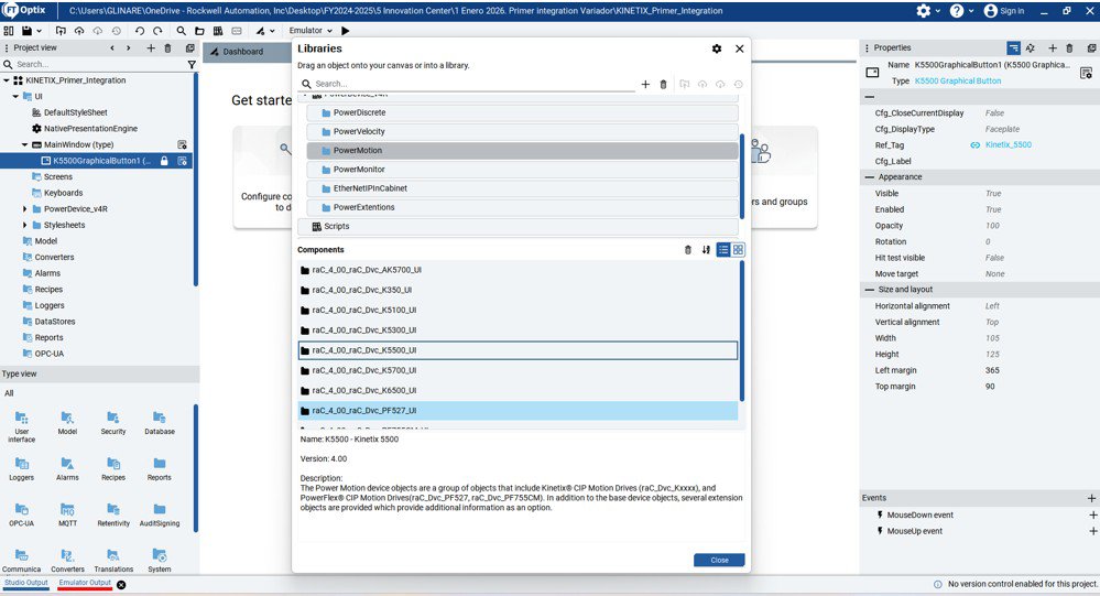
If you need multiple device objects and a “Conflicting Types Detected” dialog appears, choose:
- Skip All → to keep existing types.
- Replace All → to update to a newer version.
- Rename All → to create alternate type names.
kinetix-primer-integration_Imagen 4
Step 2.3
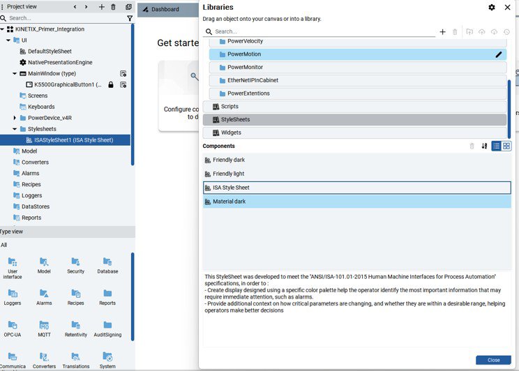
3. Copy and Configure the Style Sheet
In the UI folder, add a new subfolder named Style Sheets.
Re-open the Libraries Window and select the Style Sheets Library.
Drag the ISA Style Sheet into your new Style Sheets folder.
This style sheet follows ISA-101 HMI standards and is recommended for consistent visualization. Close the Libraries Window.
Under the UI folder, select Native Presentation Engine.
In its Properties, set Style Sheet = ISA Style Sheet.
kinetix-primer-integration_Imagen 5
Step 2.4
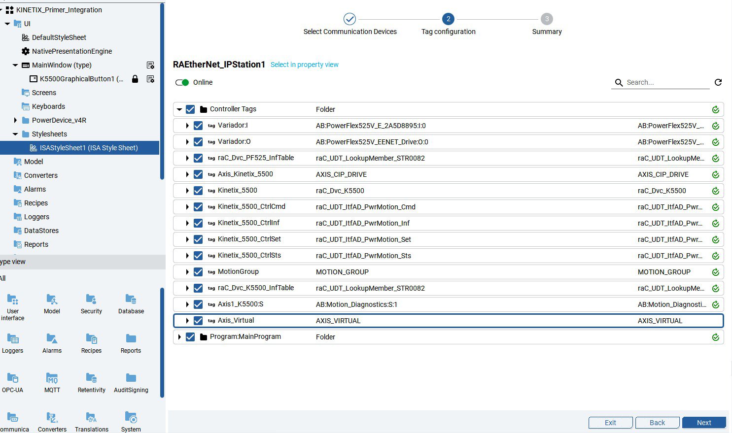
4. Configure the Communication Driver and Import Tags
If no station exists yet, open the Dashboard → Configure Communications to Devices.
- Click New Station.
- Choose RAE EtherNet/IP Station → Next.
- Enter the Controller Path and IP Address in the Root Property.
- Confirm with Next → the new station appears under Available Devices.
- Select the Configured Station in the Communication Drivers folder.
In its properties:
- Set Enable Extended Properties = True.
- Toggle Online Mode for tag import.
- The Tag Import process starts automatically.
- Review all detected controller tags.
- Select All or only required tags → Next.
When import completes, the device appears with synchronized tag data.
Click Exit to close the wizard.
kinetix-primer-integration_Imagen 6
Step 2.5
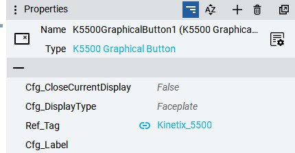
5. Configure Graphic Symbols
In your UI folder, right-click the target window or screen → New → [Library Folder] → [Device].
Under Graphic Symbols, choose the desired representation: Text Button or Graphic Button.
Link the symbol to its Add-On Instruction (AOI) instance: Select the button → set Reference Tag by browsing to the device object tag.
For Configuration Label:
Leave blank to auto-populate from tag description metadata, or Enter a custom string. Keep all other parameters as default.
kinetix-primer-integration_Imagen 7
Step 2.6
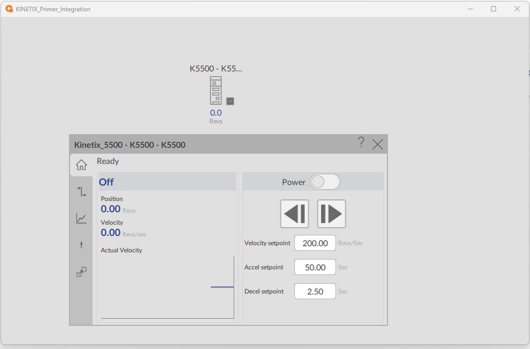
6. Save the Project and Create Runtime
When ready to test, click the Emulator drop-down → Local.
Press + to add a New Target Device.
Fill in:
- Target Name
- IP Address
Destination Path of the target Optix Panel
Run the emulation.
kinetix-primer-integration_Image 8
Kinetix Primer Integration
Version 1.2 - June 2026