
Scaling
Scaling helps to command the motor/Axis with meaningful Engineering Units (EU) such as
millimeters, inches, or degrees using the tag C.Axisxx.UnitsPerRevolution.
The
Engineering Units per Revolution
parameter defines the amount of load movement
in Engineering Units (EU) for one complete motor revolution.Scaling is applied to all tags that indicate position/distance, speed/velocity, and
acceleration/deceleration.
Linear Axis Scaling
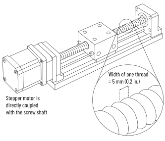
In this example, if one motor revolution moves a linear axis by 5 mm, the
Engineering Units per Revolution
value should be set to 5
.Linear Axis Scaling Example
In a linear axis, the scaling parameters can be set as follows.
Linear Axis Scaling Example
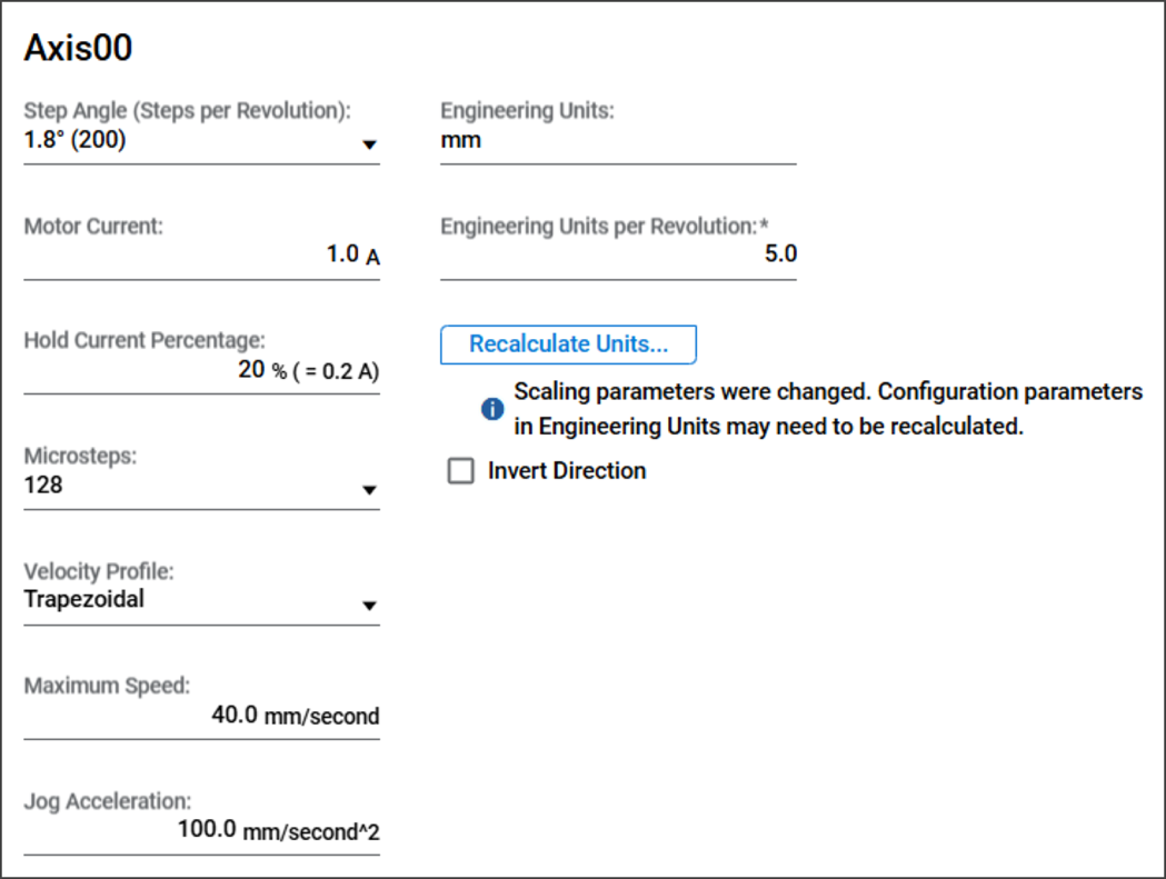
For relative Move Position command with
O:TargetPosition = 20.0 (mm)
, the
drive generates pulses for: 20 (O:TargetPosition) ÷ 5 (Engineering Units per Revolution) x 200 (Steps) x 128
(Microsteps) = 102,400 microsteps
Rotary Axis Scaling
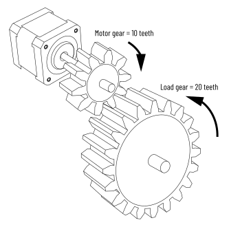
For a geared rotary system, the Engineering Units per Revolution are calculated based
on the gear ratio. If the motor drives a 10-tooth gear connected to a 20-tooth load
gear, one motor revolution (360°) produces 180 degree of load rotation. Therefore,
the
Engineering Units per Revolution
parameter should be set to 180
,
indicating that each motor revolution moves the load by 180 engineering units
(degrees).Calculation for Rotary Axis Scaling

In this example, if one motor revolution rotates a load by 180°, the value should be
set to
180
.Rotary Axis Scaling Example
In a rotary axis, the scaling parameters can be set as follows.
Rotary Axis Scaling Example
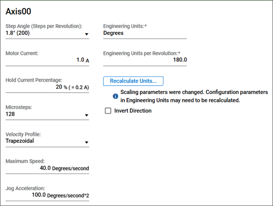
In Relative Move Position command with
O:TargetPosition = 45 (°)
, the drive
generates pulses for:45 (O:TargetPosition) ÷ 180 (Engineering Units per Revolution) x 200 (Steps) x 128
(Microsteps) = 6400 microsteps
Provide Feedback