
XX – Output, Logic Controlled View
Use XX – Output, Logic Controlled to view or configure the points for the device.
XX – Output, Logic Controlled View Example
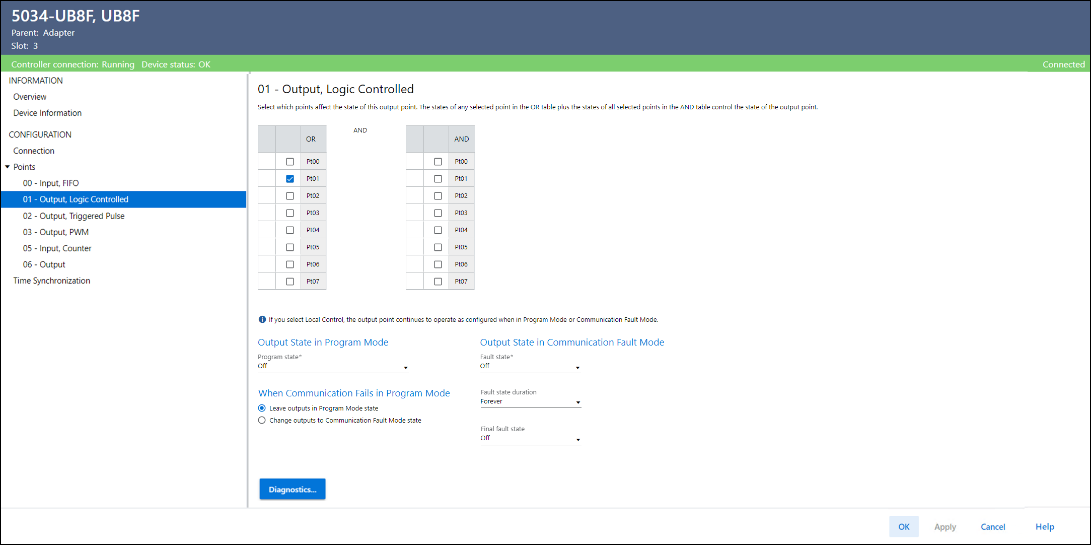
The XX – Output, Logic Controlled view includes these parameters:
Parameter | Description |
|---|---|
OR | Specifies whether Ptxx.Data participates in the OR logic
calculation. Select which points affect the state of this output point. The
state of the output point is determined by the logical OR of the
selected points in the OR table, combined with logical AND of
the selected points in the AND table. You can select multiple points, each configured in one of the
following modes, to participate in the logic calculation:
|
AND | Specifies whether Ptxx.Data participates in the AND logic
calculation. Select which points affect the state of this output point. The
state of the output point is determined by the logical OR of the
selected points in the OR table, combined with logical AND of
the selected points in the AND table. You can select multiple points, each configured in one of the
following modes, to participate in the logic calculation:
|
Output State in Program Mode Program State | Determines the behavior of each output when the controller
transitions to Program Mode or Inhibit mode. While in Program
Mode or Inhibit mode, outputs from the controller are ignored
and the output behaves as follows:
|
Output State in Communication Fault Mode Communication Fault State | Determines what happens to the output of each point after a
communication fault occurs and the module enters Communication
Fault Mode.
|
Output State in Communication Fault Mode Communication Fault State Duration | Determines the length of time the Communication Fault Mode is
held before the Final Fault State. |
Output State in Communication Fault Mode Final Communication Fault State | Determines whether the module transitions to On or Off after the
Communication Fault Mode Output State Duration elapses. The
default final state is Off. If you choose Forever for Duration, you cannot choose a final
state. The module retains its current Communication Fault Mode
state. |
Output State When Communication Fails in Program Mode | Determines the output action if communication fails in Program
Mode.
|
Diagnostics | Opens the Diagnostics dialog, which contains diagnostic
information. |
Provide Feedback