
Home Operation
Home is the operation that establishes the actual position of a configured axis by
performing a home routine, allowing the controller to synchronize the axis position with
a known reference.
Home is required because most systems do not inherently know their absolute position when
powered on and can only track movement relative to a starting position.
Home is used to define a position that correlates with the actual physical position to
help achieve accurate and repeatable motion.
The position is invalid (I.Axisxx.PositionValid = 0) when:
- The axis is disabled (powered off)
- The axis is in Motor Torque Off state
- An axis fault is present (for example, short circuit, critical temperature)
- A Field Power Loss condition is present
The position becomes valid (I.Axisxx.PositionValid = 1) when:
- Set Home Position command is successful
- Home command is completed successfully.
For information on how to use Home, see the command Home.
An axis in the home position is detected using a limit switch that is connected to a
digital input. The following figure shows how a limit switch is used in the Home
operation.
Home Operation Using Home Limit Switch
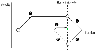
Step | Description |
|---|---|
 | Move in O:HomeDirection at C:HomeSpeed until the home switch is
detected. |
 | Decelerates to stop. |
 | Move in opposite direction at C:HomeSpeed until the home switch
goes On then Off. |
 | Decelerates to stop. |
 | Return to the home switch at C:HomeFinalSpeed. |
When the Home command starts, the I.Axisxx.PositionValid tag is cleared. When all steps
are completed, the current position is set to O.Axisxx.HomePosition and
I.Axisxx.PositionValid is set.
You can configure a timeout for finding the home position. If the axis is unable to find
the home position after the timeout elapses, the axis stops and I.Axisxx.PositionValid
remains clear.
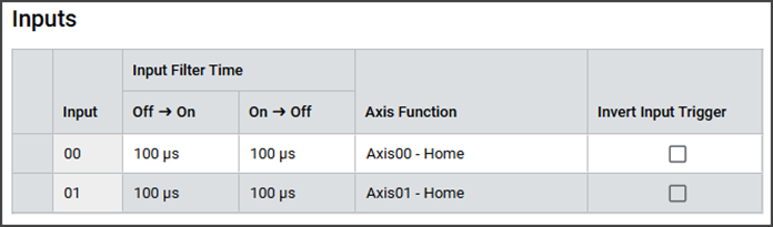
Use Local Input as Home Limit Switch
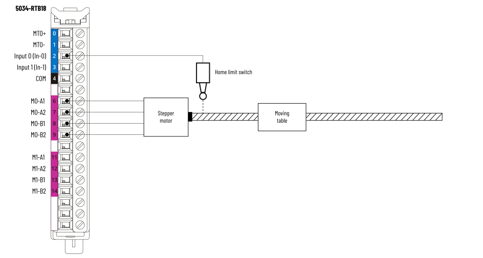
You can configure one of the stepper module's digital input points as the axis' home
limit switch in the Inputs view. You must also configure the input filter settings.
If the input is active low, you can invert the trigger by selecting the Invert Input
Trigger checkbox.
Configure Inputs as Home Limits Example
Home Limit Wiring Example
Use External Input as Home Limit Switch
You can also use a digital input point from another module (for example, 5034-IB16)
to connect the Home limit switch. In this scenario, the result of the digital input
is used to set the O.Axisxx.HomeSwitch tag. O.Axisxx.HomeSwitch cannot be inverted
and always triggers on a rising edge.
The following example shows an input point (Pt00) of the 5034-IB16 module in slot 3
is used as the Home limit switch. The 5034-STEPD module is in slot 2.
Home Limit Ladder Diagram Example

Provide Feedback