
Safety Output Modules in CIP Safety Systems
The following apply to the safety outputs:
- You can connect safety devices, such as safety relays, safety contactors.
- An external wiring short-circuit check between channels or supply is possible when the safety output is configured as Safety Pulse Test mode. The detection of external wiring fault is ≤ 1024 msec.
- Diagnostics. See Status and Fault Information in Module Properties.
- Safety output points are configured as the following:
- Not Used
- Safety
- Safety Pulse Test
Safety Mode and Safety Pulse Test Mode
The Safety Output can be configured to two types of point modes:
- Safety Mode
- Safety Pulse Test Mode
Safety Mode
When the safety output is configured to Safety Mode, a warning message prompt
occurs.
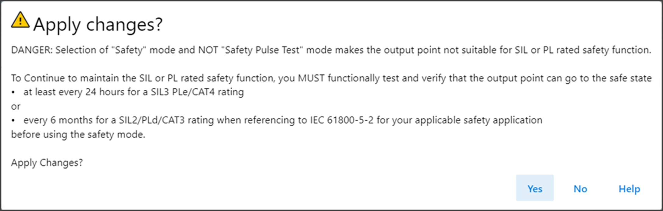
You are responsible to command the Safety Output to Safe State at the stated
interval in order to achieve the desired safety level.
Safety Pulse Test Mode
When the safety output is configured to Safety Pulse Test Mode, the safety output
channel continuously test the ability of the safety output to remove power from the
output terminals of the module. The safety output turn off momentarily during the
pulse test duration.
If an error is detected, the safety output data and individual safety output status
turn off.
Safety Output Voltage Variation During Pulse Test When Safety Pulse Test
Mode is Configured
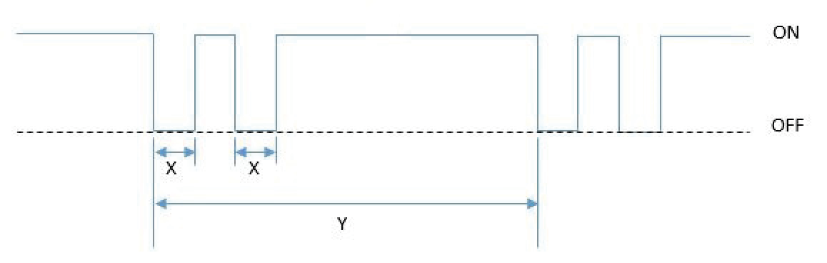
On the safety output modules, the pulse width (X) is less than 700 μs, and the pulse
period (Y) is less than 524 ms.
TIP:
To help prevent the test pulse from causing the connected device to
malfunction, pay careful attention to the input response time of the output
device.
See Wiring Diagrams for Safety Mode and Safety Pulse Mode for more details about applying Safety Mode and Safety Pulse Test Mode in your
application.
Single-channel Mode
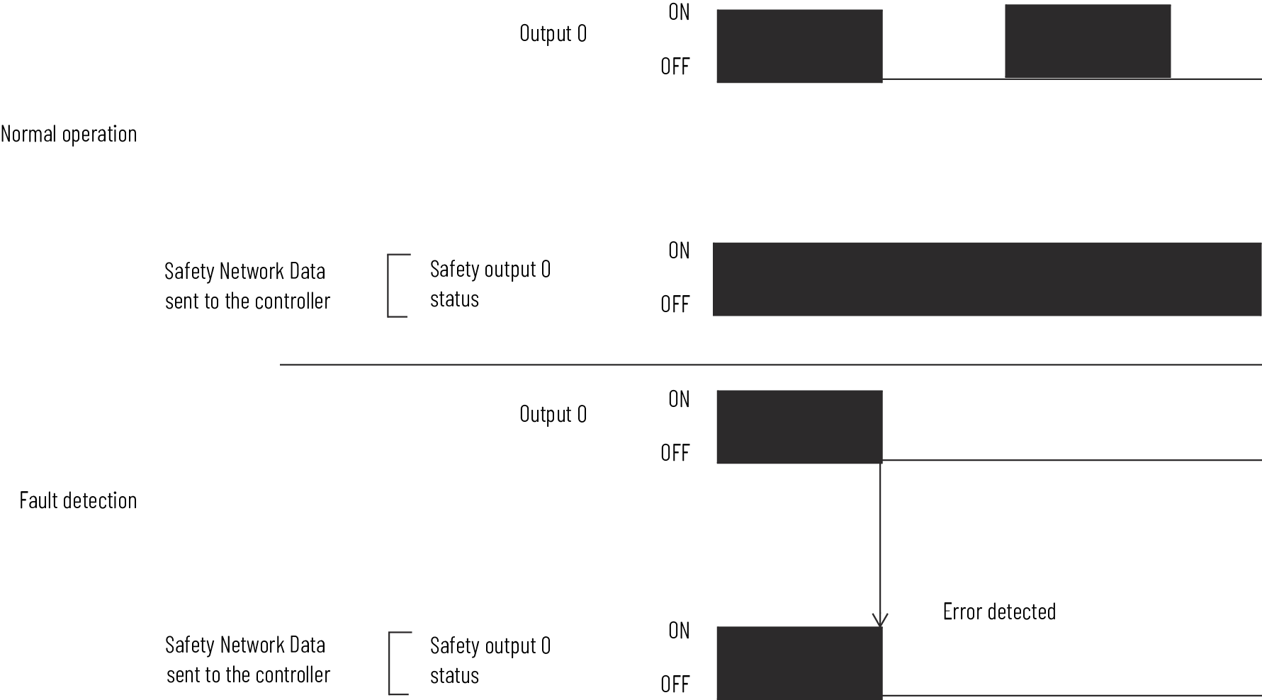
When the output channel is in the On state and without any faults, the safety outputs
turned on. The status is normal. If a fault is detected on the output channel, the
safety output is de-energized and individual safety output status turn off.
Single-channel Normal Operation and Fault Detection (Not to
Scale)
Dual-channel Mode
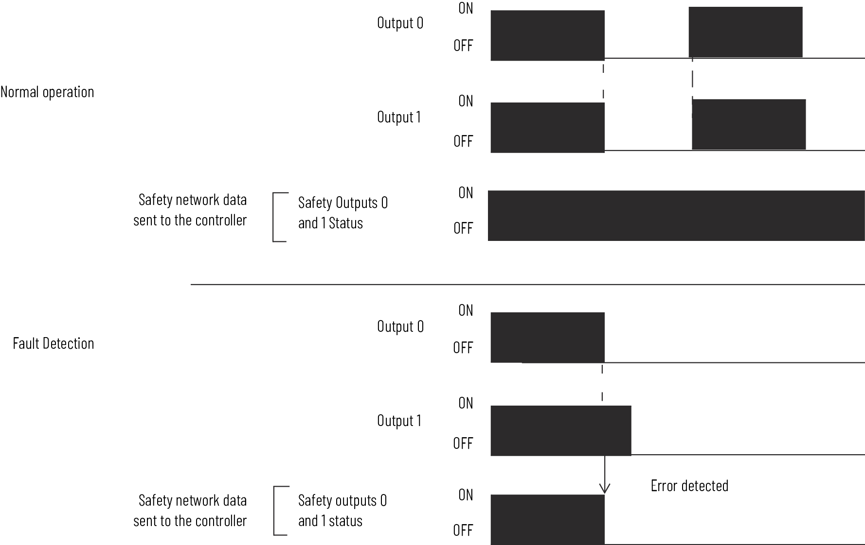
When dual-channel mode is used, output channels function as connection pairs.
Connection pairs are as follows:
- Channels 0 and 1
- Channels 2 and 3
- Channels 4 and 5
- Channels 6 and 7
When both output channels in a connection pair are in the On state and without any
faults, the safety outputs are turned on.
Dual-channel Normal Operation and Fault Detection (Not to Scale)
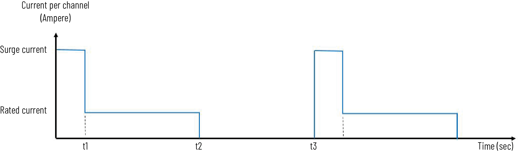
Surge Capability of Safety Output
The safety output supports temporary surge of current when transitioning from OFF to
ON.
Surge Capability
Safety Output Fault Reset
The I/O channel supports a module-level user-configurable ‘Latch Fault until reset
via output tag’ mode and recovers from only these field faults:
- Safety Output Overload
- Safety Output NoLoad
TIP:
Other types of Safety Output faults are non-recoverable. You must cycle power
to the module.
Latch Fault until Reset via Output Tag mode is Enabled
When Latch Fault mode is Enabled, the I/O channel holds safety output fault
indications until it checks that the field fault is removed. If the field fault is
removed, the channel clears the fault status only upon detecting that the ResetFault
in its consume assembly channel sees a rising edge.
Latch Fault until Reset via Output Tag mode is Disabled
When Latch Fault mode is Disabled (default), the I/O channel holds safety output
fault indications for 1 second until it checks if the field fault is removed. If the
field fault is removed, the channel clears the fault status only upon detecting the
consume data bit is low. The fault status can also be cleared by a module reset or
power cycle.
After the channel clears the fault, the I/O indicator (red) turns off. The output
data can now be controlled.
IMPORTANT:
If the module outputs experience persistent high faults, consider cycling
power to the module to clear the error.
Provide Feedback