
5034-IB16 and 5034-IB16XT Digital 16 Input Modules
5034-IB16 and 5034-IB16XT Wiring Diagram
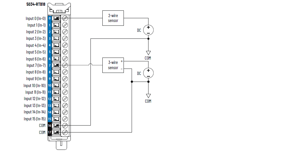
To establish more COM connections, install a 5034-MBPTM or 5034-MBPTMXT next to the
module. You can install up to two 5034-MBPTM or 5034-MBPTMXT modules consecutively
to the right of the digital 16 input module for 3-wire sensor applications.
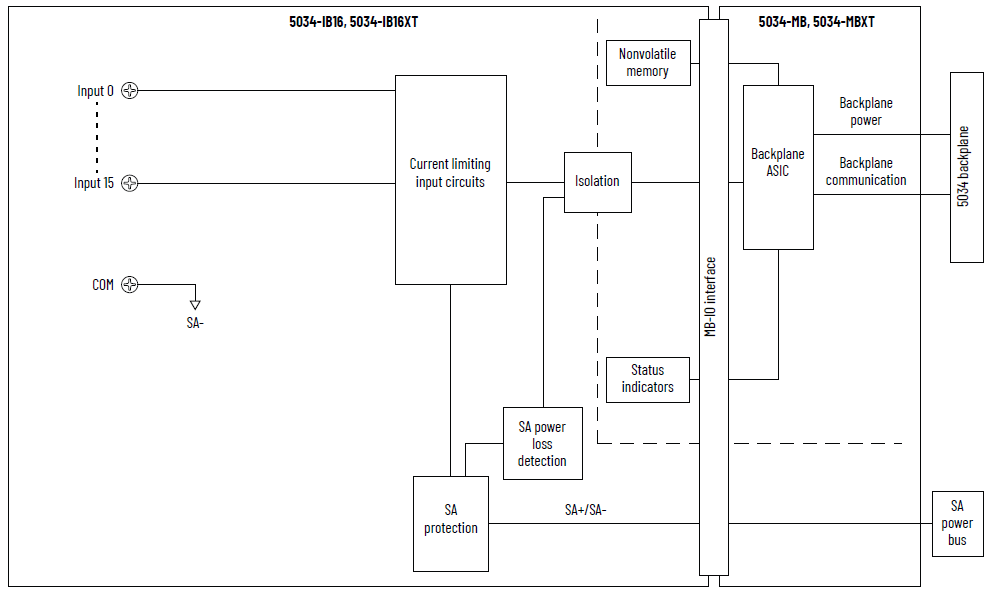
5034-IB16 and 5034-IB16XT Functional Block Diagram
Attribute | 5034-IB16, 5034-IB16XT |
|---|---|
On-state voltage range | 10…30V DC |
On-state current, min | 2 mA |
On-state current, nom | 2.4 mA |
On-state current, max | 2.8 mA |
Off-state voltage, max | 5V DC |
Off-state current, max | 1.5 mA |
Input impedance, min | 3.57 kΩ @ 10V DC |
Input impedance, nom | 10 kΩ @ 24V DC |
Input impedance, max | 15 kΩ @ 30V DC |
Input delay time (screw to backplane), max Off-to-On On-to-Off | 150 µs |
Input pulse width, min Off-to-On On-to-Off | 125 µs |
Input filter time Off-to-On On-to-Off | 0 µs, 100 µs, 200 µs, 500 µs, 1 ms (Default), 2 ms, 5 ms, 10
ms, 20 ms, 50 ms |
Simple counters, counter frequency | 0…f max = 4000 Hz4 (with 12 points as standard inputs) or 8 (with 8 points as
standard inputs) Point 0…7 only |
Timestamp of inputs (sequence of events) | Yes, ±100 µs accuracy |
Events | Not supported |
Attribute | 5034-IB16, 5034-IB16XT |
|---|---|
Number of inputs | 16 channels (1 group of 16), sinking |
Voltage category | 12/24V DC sink |
Input voltage, nom | 24V DC |
Input voltage range | 10…30V DC |
SA power voltage, nom | 24V DC |
SA power voltage range | 10…30V DC |
SA power current, nom | 20 mA |
SA power current, max | 0.1 A |
SA power current at no load | 10 mA |
SA reverse polarity protection | Yes |
Power dissipation, max (1) | 1.45 W |
Thermal dissipation, max (1) | 4.95 BTU/hr |
Isolation voltage | 250V (continuous), Basic Insulation Type,
System (2) to FieldNo isolation between SA power and inputs No isolation between individual inputs |
RIUP support | Yes |
CIP Sync | Yes, slave only ordinary clock |
Electronic keying | Electronic keying via programming software |
RTB key positions (slot) | 1, 4, 11 |
RTB supported | 5034-RTB18, 5034-RTB18S |
Wiring category (3) | 2 - Signal ports 2 - Power ports |
Wiring specification | See Wiring Specifications for Removable Terminal Blocks in
the PointMax I/O System Specifications Technical Data,
publication 5034-TD001 |
Indicators | 1 green/red module status indicator 1 green/red SA power status indicator 16 yellow I/O status indicators |
Dimensions (HxWxD), approx | 123.6 x 15.0 x 66.4 mm (4.87 x 0.59 x 2.61 in.) |
Weight, approx | 43.0 g (1.52 oz.) – 5034-IB16 45.0 g (1.59 oz.) – 5034-IB16XT |
Enclosure type | None (Open-style) |
North American temp code | T4 |
UKEX/ATEX temp code | T4 |
IECEx temp code | T4 |
(1) Value is measured at 60 °C (140 °F). Power dissipation
varies with temperature. (2) For the System to Field isolation attribute, System
refers to the backplane and Field refers to the SA side of
the module. Unless otherwise specified, this definition
applies to all modules. (3) Use this Conductor Category information for planning
conductor routing. See the Industrial Automation Wiring and
Grounding Guidelines, publication 1770-4.1. Use this
Conductor Category information for planning conductor
routing as described in the appropriate System Level
Installation Manual. | |
Provide Feedback