
General
This "Basic Module Information" (BMI) provides quick access to a list of the main module functions, some attributes, and the location of more detailed module information.
NOTE
: When developing an application, or troubleshooting a significant problem, it is
IMPORTANT
to read and follow more detailed module information, including safety recommendations.
The primary source of detailed module information is the "Full User Guide ACT350 Transmitter" available from http://us.mt.com/us/en/home/supportive_content/product_documentation/datasheets/ACT350.html. This is referred to as the "manual" in this BMI.NOTE: In this BMI, the word "tag" refers to data tags in the Logix controller.
Function
The ACT350 EtherNet/IP interface enables the ACT350 to communicate to EtherNet/IP Programmable Logic Controllers (PLCs) through a direct connection to the EtherNet/IP network at 100 MBPS speed. The ACT350 consists of a DIN Rail mounted unit with a built-in Ethernet/IP interface. Various types of data exchange to allow reading and writing of different weighing and control parameters for the ACT350 are available. Configuration to setup the type of data exchange resides in the ACT350, and is also available by using the Setup+™ PC Tool-based setup.
Features
- User programmable IP address, Subnet Mask and Gateway address.
- Unicast I/O for EtherNet/IP allows for direct point-to-point communication between two devices on a network. This communication format is more efficient when I/O data does not need to be shared between multiple target devices.
- Capability for bi-directional discrete mode communications (Class 1 Cyclic Messaging) of weight or display increments (in integer or floating point format), status, and control data between the PLC and the ACT350.
- Support for Explicit Messaging to access ACT350 internal variables.
- Offers specific Data Okay and Heartbeat bits to allow the PLC to confirm that data exchange is valid and working.
- 1-Block or 2-Block connection options allow selection of compact communications or detailed device status.
- Status LEDs to indicate communication, network and module status.
Network Connectors
Refer to manual for pinouts and Rockwell Automation part numbers of mating connector.
- The wiring between the PLC and the ACT350 EtherNet/IP Interface kit uses a standard ethernet twisted pair cable with a RJ-45 connection. Cables are not supplied by Mettler-Toledo.
- The cable installation procedures and specification including distance and termination requirements are the same as recommended by Allen-Bradley for the EtherNet/IP network.
Module Identity
The module Identity includes the following Device attributes:
- Vendor ID '666', and Vendor Name string 'METTLER TOLEDO'
- Product Type '12', and Product Type Name string 'Communications Adaptor'
- Product Code '13057', and Product Name string 'ACT350'
- Catalog Name string 'MT-30076690'
Communications
The ACT350 EtherNet/IP Interface uses EtherNet/IP Implicit communication for transferring I/O data to a controller. Certain data can also be accessed using EtherNet/IP explicit messaging. CIP messages are supported from a host device over the EtherNet/IP network.
Note
: Refer to the manual for full details of these communication protocols.Input and Output Tag Data
The ACT350's PLC I/O Interface is based on the Mettler Toledo Standard Automation Interface (SAI). This interface provides a standard protocol for all Mettler Toledo devices so that the user can access them in the same way, and expect that they respond to the same basic set of commands.
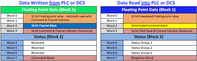
The ACT350 implements two modes of cyclic data communications. Those modes are referred to as 1-Block and 2-Block format.

1-Block
Format (shown above) is the most basic method of communicating using the SAI protocal. It returns a Single Precision Floating Point value from the device, along with command and scale status words, for a total of four words (8 bytes). Four words (8 bytes) of output data are also provided so that a Single Precision Floating Point command value can be sent to the device, along with a 16-bit command word.In devices that have more than one channel, the 16 bit Channel Mask can be used to send the same commands to more than one channel at the same time. Since the ACT350 is a single channel device, the Channel Mask is usually ignored. However, there are some special commands (such as the Test Command) that require this value to be populated. Because the Channel Mask can still sometimes take on a function and impact how the device responds, it is recommended that the value always be set to zero when not using one of the special commands.
2-Block
Format (shown above) provides a total of 8 words (16 bytes) of I/O in both directions by using the basic 1-Block format, and adding another 4 words (8 bytes) of status information.From a functional standpoint, only a Command Word is added to the Controller Outputs in 2-Block format. The Command Word is used to tell the device which combinations of status words should be returned to the Controller. The remaining Output words are currently reserved for future use.
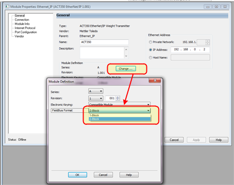
Select 1-Block or 2-Block format from the AOP using the Drop-down box shown below by clilcking on the "Change" button in the AOP. But also be sure to make the same selection in the setup of the ACT350 itself, or the unit may fail to connect due to an I/O Connection Size mismatch.
Note
: Logix IO tags are updated by the controller asynchronous to its ladder-logic program scan. When "block integrity" of this data is important, the CPS ladder instruction can synchronously copy the data to other Logix tags for use by application logic. Note
: Default RPI
for the IO connection is 10ms
. It is important to set the Requested Packet Interval for an update time suitable for the application. The update time chosen determines how often the host will receive Input Image updates from the ACT350 EtherNet/IP Interface. A very long RPI will result in events taking place at the ACT350 EtherNet/IP Interface module that may never be seen by the host logic.1 Block Format Tags
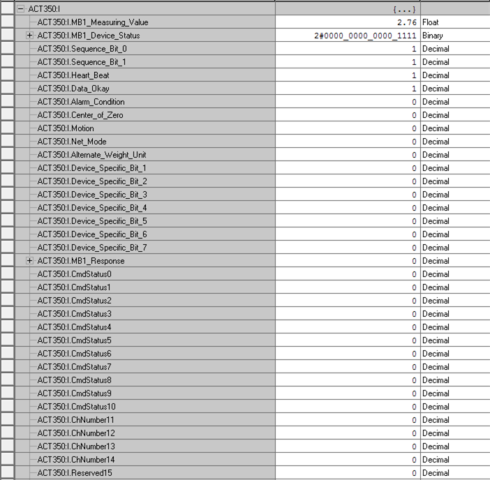
Below is the view of an ACT350 device
1-Block Input tags
. Note that the Floating Point value returned from the device can be accessed with the MB1_Measuring_Value
tag. The Scale Status bits can be access as a word with the MB1_Device_Status
tag, or by accessing the individual bit tags expanded below it. The MB1_Response
tag will echo back the last command sent to the device after the command has been accepted. 1 Block Input Tags
Below is the view of an ACT350 device
1-Block Output tags.
Note that the Floating Point value written to the device can be accessed with the MB1_Command_Value
tag. The actual command sent to the device is written in the tag MB1_Command
MB1_Channel_Mask
(and the corresponding bit tags below it) are not used on the ACT350 since it is a single channel device - except for some special commands such as the Test Mode.1 Block Output Tags

2 Block Format Tags
2 Block format takes the 1 Block tags and adds the Status Command on the PLC/DCS Output, and the Status Group words with Response Word on the PLC/DCS Input.
Below is a view of the ACT350 Status Block tags added onto the
1 Block
tags to make up the 2-Block Input format. The bits in the individual status groups will change meaning depending on what Status Block Command is being sent by the PLC/DCS system in the Outputs. The PLC programmer will need to use care when looking at these bits to ensure that the bit interpretations take the command response (SB1_Response
) value into account to understand the proper meaning.2 Block Input Tags

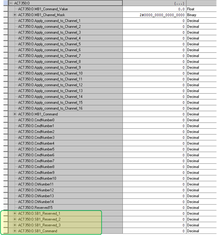
Below is the view of an ACT350 device
2-Block Output
tags. Note that the Status Block is appended after the 1-Block
tags, so that both structures are now present. The first three words of the StatusBlock are reserved for future use. The last word is a Command value from the Controller to the ACT350 to select predefined combinations of Status Words to be returned to the Controller's Inputs. Please refer to the manual for details the definitions for the commands and the status bits returned in each Status Word.2 Block Output Tags
Provide Feedback