
Pulse Width Modulation
Pulse width modulation (PWM) provides precise, onboard control of an output’s pulse train
with no program variability. To configure a PWM signal, you define two real-time values
for the pulse train in the module’s output tags:
- Cycle time — The duration of a pulse cycle.
- Duty cycle — The percentage of the cycle time that a pulse is active.
If the cycle time or duty cycle value changes while the output is generating a PWM
signal, the changes are not applied until the next cycle of the PWM output. For example,
if the duty cycle is 10% and the cycle time is 1.0 second and the cycle time is changed
to 0.5 second just after the output turns On, the output stays On for 0.1 second and
then turns Off for 0.9 seconds to complete the cycle before the new 0.5 second cycle
begins.
For another example, if the cycle time is erroneously set to an hour, a new cycle time
does not go into effect until the current cycle of the hour is complete. To trigger the
PWM output to restart immediately with a new cycle time or duty cycle, turn off the
output and then it back On.
If the cycle time or pulse width (that is, cycle time * duty cycle or cycle time * [100%
- duty cycle]) is outside the valid range for an output, the
I.Ptxx.Error
tag is
set and the module responds as described in the following table.Condition | Result |
|---|---|
CycleTime < Minimum cycle time | CycleTime = Minimum cycle time |
CycleTime > Maximum cycle time | CycleTime = Maximum cycle time |
Duty Cycle > 100% | Output is always in Active state. |
Pulse width < Minimum pulse width | Output is always in Idle state. |
IMPORTANT:
Before PWM functions, you must enable PWM in the module configuration.
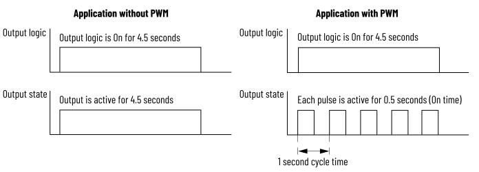
The figure below compares two applications in which the output is instructed to turn On
for 4.5 seconds:
- In the application without PWM, a single pulse is generated. The pulse remains active for the same length of time the Data output tag is On (4.5 seconds).
- In the application with PWM, a series of pulses is generated. Each pulse is active for a configured pulse width of 0.5 seconds or 50% of the 1 second cycle time. The Data output tag is On for 4.5 seconds.
PWM Timing
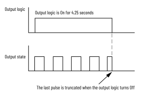
By default, PWM is configured to continue the output pulse train until the output logic
(
O.Ptxx.Data
tag) turns Off. When the output logic turns Off, the output
pulse train immediately stops.For example, in this figure, the output logic is On for 4.25 seconds and then turns Off
in the middle of the last pulse. Even though the pulse width is configured for 0.5
seconds, the last pulse is only active for 0.25 seconds because it is truncated when the
output logic turns Off.
PWM with Truncated Pulse
IMPORTANT:
When the module goes into Program Mode, Communication Fault mode, or is
inhibited, the Program Mode and Communication Fault Mode states that are
configured for the module override the PWM output state.
You can modify the default PWM configuration for further control of an output’s pulse
train.
Idle State
The Idle state indicates the output state when the PWM pulse sequence is not running
(PWM is idle).
Output in PWM Idle State

Enforce PTO Duty Cycle
You can limit the duty cycle to be always 50% by enabling the Enforce Duty Cycle at
50.0% for Pulse Train Output (PTO).
When this configuration is enabled, the
O.Pwmxx.DutyCycle
tag is ignored and
generated pulse cycles have 50% duty cycle.Cycle Count and Execute All Cycles
You can limit the number of pulse cycles that occur while an output is On. This
feature is useful when you want to apply a level of output control when a process is
stopped. For example, in a gluing application, you may want to apply four drops of
glue to a product when the product is within a fixed window on a conveyor belt. By
configuring a cycle count of four, you can make sure that only 4 drops of glue are
applied even if the conveyor belt stops with the product in the window. Controlling
the process with the Cycle Count feature eliminates the need to write complex logic
to detect a stopped conveyor belt.
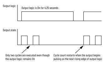
The following figure shows a PWM pulse train that is configured with a cycle count of
2. When the cycle count is reached, the PWM pulse train is stopped and the
I.Pwmxx.Active
tag is cleared.PWM Cycle Count
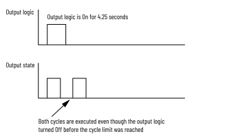
If the output logic turns Off before the cycle limit is reached, you can configure
the pulse cycles to continue until the cycle limit is reached by enabling the
Execute All Cycles option. The following figure shows a cycle limit of 2 with the
Execute All Cycles option enabled.
IMPORTANT:
When changing cycle count, you should turn off the output first or wait for
the Active input tag to turn off. Otherwise, an additional pulse may be
generated.
PWM Cycle Count with Execute All Cycles Option
Provide Feedback