
5034-IA8 and 5034-IA8XT Digital 8 AC Input Modules
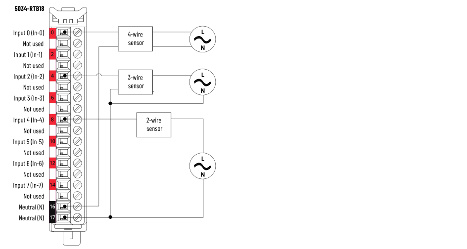
5034-IA8 and 5034-IA8XT Wiring Diagram
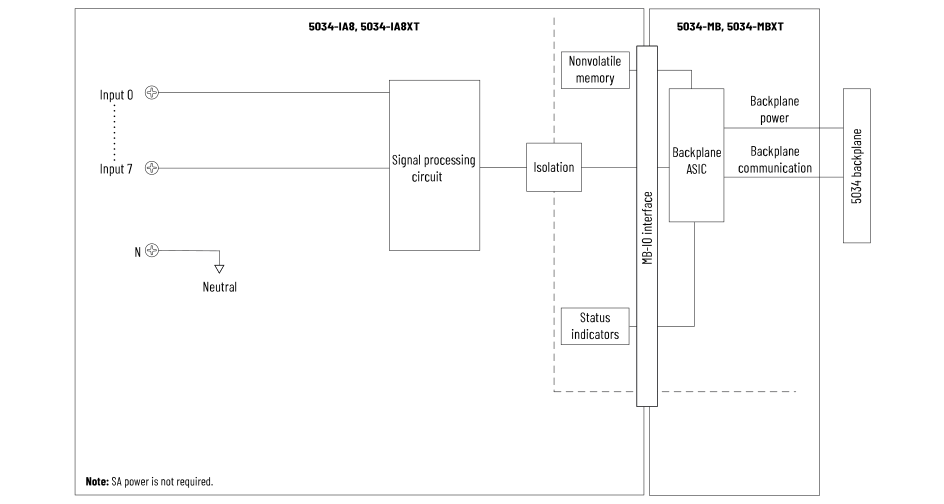
5034-IA8 and 5034-IA8XT Functional Block Diagram
Attribute | 5034-IA8, 5034-IA8XT |
|---|---|
On-state voltage, min | 74V AC |
On-state voltage, nom | 120/240V AC |
On-state voltage, max | 264V AC |
Off-state voltage, max | 40V AC |
On-state current, min | 3.5 mA @ 74V AC 5 mA @ 159V AC |
On-state current, nom | 7.5 mA @ 120V AC 50/60 Hz 13.5 mA @ 240V AC 50/60 Hz |
On-state current, max | 15 mA @ 139V AC 50/60 Hz 15 mA @ 264V AC 50 Hz 17 mA @ 264V AC 60 Hz |
Off-state current, max | 3 mA |
Input impedance, nom | 17.5 kΩ @ 120V AC 50/60 Hz 17.0 kΩ @ 240V AC 50/60 Hz |
Input impedance, min | 11 kΩ @ 264V AC/63 Hz |
Inrush current, max | 600 mA |
Input delay time (screw to backplane), max Off-to-On On-to-Off | 12 ms |
Input filter times (1) Off-to-On | User-selectable filter times:
|
Input filter times On-to-Off | User-selectable filter times:
|
(1) For the 5034-IA8/XT module, the Studio 5000 Logix
Designer application lets you select multiple filter
values, including values that are invalid for some input
signals. For example, 1 ms is the only valid Off-to-On
filter value when a 120V AC signal is connected to the
module. However, the Studio 5000 Logix Designer
application lets you select 1 ms, 2 ms, or 5 ms. If you
select an invalid filter value, the module can read
signal levels incorrectly. For more information, see the PointMax Digital I/O
Modules User Manual, publication 5034-UM002. | |
Attribute | 5034-IA8, 5034-IA8XT |
|---|---|
Number of inputs | 8 channels (1 group of 8) |
Voltage category | 120/240V AC |
Input voltage range | 74…264V AC |
Input voltage frequency | 47…63 Hz |
Power dissipation, max (1) | 1.25 W |
Thermal dissipation, max (1) | 4.26 BTU/hr |
Isolation voltage | 250V (continuous), Reinforced Insulation Type,
System (2) to FieldNo isolation between individual inputs |
RIUP support | Yes |
CIP Sync | Yes, slave only ordinary clock |
Electronic keying | Electronic keying via programming software |
RTB key positions (slot) | 5, 13, 15 |
RTB supported | 5034-RTB18, 5034-RTB18S |
Wiring category (3) | 1 - Input ports 1 - Power ports |
Wiring specification | See Wiring Specifications for Removable Terminal Blocks in
the PointMax I/O System Specifications Technical Data,
publication 5034-TD001 |
Indicators | 1 green/red module status indicator 8 yellow I/O status indicators |
Dimensions (HxWxD), approx | 123.6 x 15.0 x 66.4 mm (4.87 x 0.59 x 2.61 in.) |
Weight, approx | 43.0 g (1.52 oz) – 5034-IA8 47.0 g (1.66 oz) – 5034-IA8XT |
Enclosure type | None (Open-style) |
North American temp code | T4 |
UKEX/ATEX temp code | T4 |
IECEx temp code | T4 |
(1) Value is measured at 60 °C (140 °F). Power dissipation
varies with temperature. (2) For the System to Field isolation attribute, System
refers to the backplane. (3) Use this Conductor Category information for planning
conductor routing. See the Industrial Automation Wiring
and Grounding Guidelines, publication 1770-4.1. Use this Conductor Category information for planning
conductor routing as described in the appropriate System
Level Installation Manual. | |
Provide Feedback