
5034-OA4 and 5034-OA4XT Digital 4 AC Output Modules
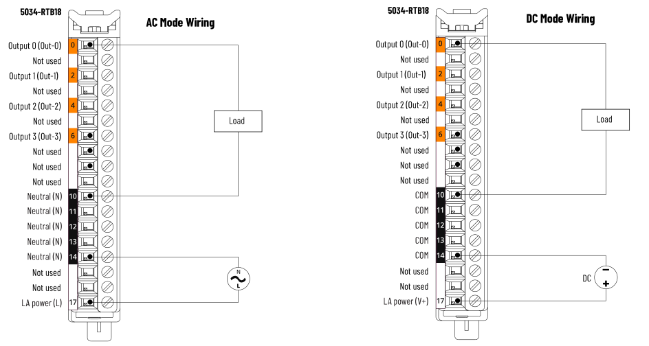
5034-OA4 and 5034-OA4XT Wiring Diagram
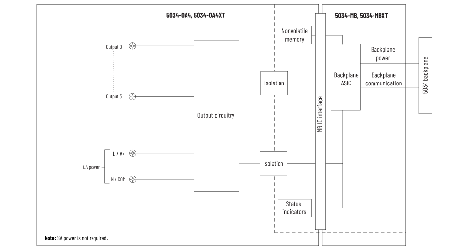
5034-OA4 and 5034-OA4XT Functional Block Diagram
Attribute | 5034-OA4, 5034-OA4XT (1) | |
|---|---|---|
AC Mode | DC Mode | |
On-state voltage, min | 85V AC | 10V DC |
On-state voltage, nom | 120/240V AC | 240V DC |
On-state voltage, max | 264V AC | 250V DC |
On-state voltage drop, max | 1.5V AC @ 0.75 A | 1.5V DC @ 0.75 A |
Output current per point, min | 5 mA | |
Output current per point, max | 0.75 A | |
Output current per module, max | 3 A | |
Off-state leakage current, max (2) | 1 mA | |
Surge current per point | 5 A max for 25 ms, repeatable every 2 s 7 A max for 40 ms, repeatable every 8 s | 5 A max for 25 ms, repeatable every 2 s |
Output delay time (Backplane to screw) Off-to-On On-to-Off | 1/2 cycle time (typ) | 1.5 ms (typ) |
Field (LA) power loss detection | Yes | No |
Inductive load allowed per point, max | 40 mH | |
No load detection diagnostics | Not supported | |
Output short circuit/overload/overtemperature detection | ||
Output short circuit/overload protection | ||
Pilot duty rating | Resistive/General/Pilot Duty 5 A inrush current, 0.75 A rated current @ 85…264V AC, 47…63
Hz | Resistive/General/Pilot Duty 5 A inrush current, 0.75 A rated current @ 10…250V DC |
Output states in program mode per point |
| |
Output states in communication fault mode per point | ||
Duration of communication fault mode per point |
| |
Output final state after communication fault mode per point |
| |
(1) The module does not support mixed AC and DC operation.
All points operate in the same mode, either AC or DC, based
on the module configuration. (2) Recommended Loading Resistor - To limit the effects of
leakage current through solid-state outputs, connect a
loading resistor in parallel with the load during the
Off-state. For example, use a 24 kΩ, 2 W resistor for 120V
AC operation and a 48 kΩ, 5 W resistor for 240V AC
operation. | ||
Attribute | 5034-OA4, 5034-OA4XT (1) | |
|---|---|---|
AC Mode | DC Mode | |
Number of outputs | 4 channels (1 group of 4), Sourcing | |
Voltage category | 120/240V AC | — |
Output voltage, nom | 240V AC | 240V DC |
Output voltage range | 85…264V AC | 10…250V DC |
LA Power voltage range | 85…264V AC, 47…63 Hz | 10…250V DC |
LA Power current, max | 3 A @ 120/240V AC, 50/60 Hz | 3 A @ 250V DC |
Power dissipation, max (2) | 1.31 W | |
Thermal dissipation, max (2) | 4.45 BTU/hr | |
Isolation voltage | 250V (continuous), Reinforced Insulation Type, System to
Field No isolation between LA Power and Output ports No isolation between individual Output ports | |
RIUP support | Yes | |
CIP Sync | Yes, slave only ordinary clock | |
Electronic keying | Electronic keying via programming software | |
RTB key positions (slot) | 6, 13, 15 | |
RTB supported | 5034-RTB18, 5034-RTB18S | |
Wiring category (3) | 1 - Output ports 1 - Power ports | |
Wiring specification | See Wiring Specifications for Removable Terminal Blocks in
the PointMax I/O System Specifications Technical Data,
publication 5034-TD001 | |
Indicators | 1 green/red module status indicator 4 yellow/red I/O status indicators 1 green/red LA power status indicator | 1 green/red module status indicator 4 yellow/red I/O status indicators |
Dimensions (HxWxD), approx | 123.6 x 15.0 x 66.4 mm (4.87 x 0.59 x 2.61 in.) | |
Weight, approx | 44.0 g (1.55 oz) – 5034-OA4 48.0 g (1.69 oz) – 5034-OA4XT | |
Enclosure type | None (Open-style) | |
North American temp code | T4 | |
UKEX/ATEX temp code | T4 | |
IECEx temp code | T4 | |
(1) The module does not support mixed AC and DC
operation. All points operate in the same mode, either
AC or DC, based on the module configuration. (2) Value is measured at 60 °C (140 °F). Power
dissipation varies with temperature. (3) Use this Conductor Category information for planning
conductor routing. See the Industrial Automation Wiring
and Grounding Guidelines, publication 1770-4.1. Use this Conductor Category information for planning
conductor routing as described in the appropriate System
Level Installation Manual. | ||
Provide Feedback