Example: How to configure Modbus communication to read from and write to a drive
These examples describe how to configure Modbus communication to read status data from and write control data to a
PowerFlex
4 drive using the MSG_MODBUS instruction.L50E wiring
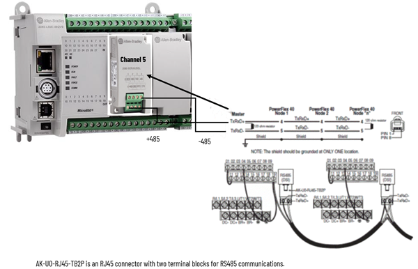
This example uses an L50E controller with a SERIALISOL module plugged into the first slot (Channel 5). A single
PowerFlex
40 is connected, but the diagram below shows how to wire for multi-drop. Refer to the user manual for additional wiring information.L50E wiring
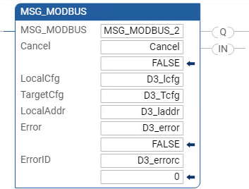
Modbus Read example
The following MSG_MODBUS instruction can be used to read status data from the
PowerFlex
40 drive.MSG_MODBUS instruction read example
Drive status
An "1807" indicates the drive is:
- Ready (bit 0 ON)
- Active (bit 1 ON)
- Commanded Forward (bit 2 ON)
- Rotating Forward (bit 3 ON)
- Status of some digital inputs on the drive
A "278" indicates 27.8Hz.
Refer to the
PowerFlex
user manual for additional information about Logic Status word bits, error code descriptions, commanded and actual speeds, and other status codes.MSG_MODBUS Read configuration
The following image shows the variable options for the MSG_MODBUS instruction block used to read status data from a
PowerFlex
40 drive.Variable options for MSG_MODBUS to read status data from a PowerFlex 40 drive
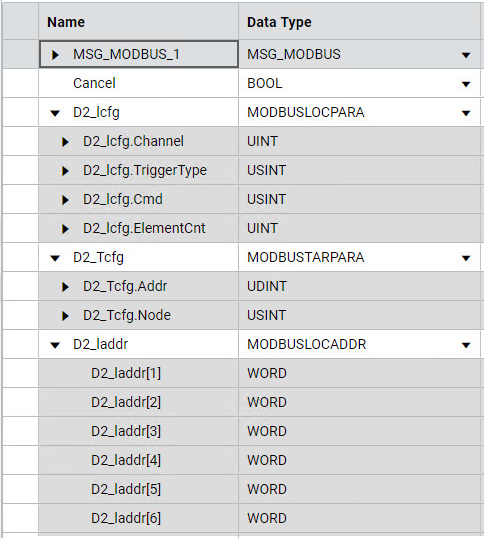
MSG_MODBUS Read variables
The following table identifies the variables and the values used to configure the MSG_MODBUS instruction to read status data from a
PowerFlex
4 drive.Variable | Value | Description |
|---|---|---|
*.Channel | 5 | Channel 5 - location of SERIALISOL module |
*.TriggerType | 0 | Trigger on False-to-True transition |
*.Cmd | 3 | Modbus Function Code "03" - Read Holding Registers |
*.ElementCnt | 4 | Length |
*.Addr | 8449 | PowerFlex Logic Status word address + 1 |
*.Node | 2 | PowerFlex Node address |
*_laddr[1] | data | PowerFlex Logic Status word |
*_laddr[2] | data | PowerFlex Error Code |
*_laddr[3] | data | PowerFlex Commanded Speed (Speed Reference) |
*_laddr[4] | data | PowerFlex Speed Feedback (Actual Speed) |
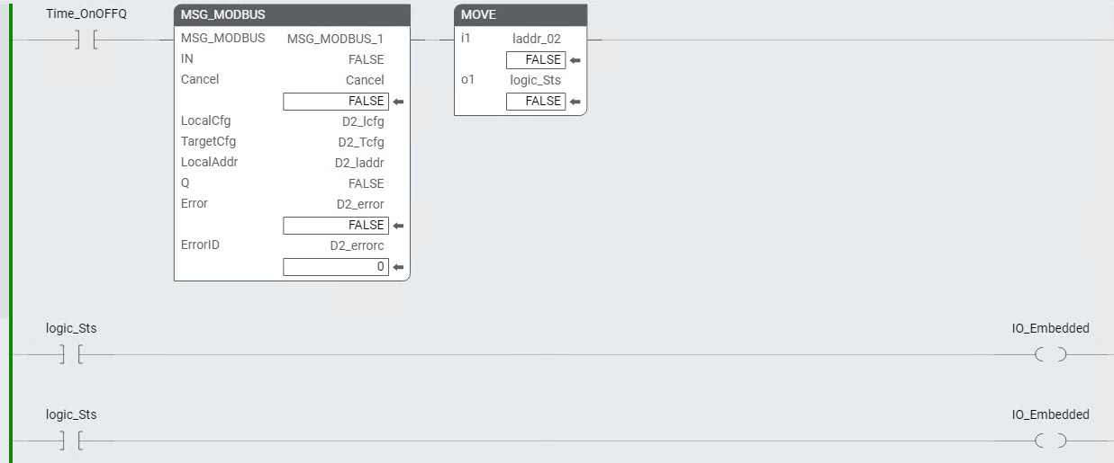
MOVE instruction example
The following image shows an example of using the MOVE instruction to move the *_l[1] array value to a Word, which allows you to directly access the individual bits.
MOVE instruction example
Modbus Write example
The following MSG_MODBUS instruction is used to write control data to a
PowerFlex
40 drive.Modbus Write example
MSG_MODBUS Write configuration
The following image shows the variables and the values used to configure the MSG_MODBUS instruction to write control data to a
PowerFlex
4 drive.MSG_MODBUS Write configuration
MSG_MODBUS Write variables
The following table lists the variables, values, and describes the purpose of each variable.
Variable | Value | Description |
|---|---|---|
*.Channel | 5 | Channel 5 - location of SERIALISOL module |
*.TriggerType | 0 | Trigger on False-to-True transition |
*.Cmd | 16 | Modbus Function Code "16" - Write Holding Registers |
*.ElementCnt | 2 | Length |
*.Addr | 8193 | PowerFlex Logic Status word address + 1 |
*.Node | 2 | PowerFlex Node address |
*_laddr[1] | data | PowerFlex Logic Command word |
*_laddr[2] | data | PowerFlex Speed Reference word |
Provide Feedback