MSG_MODBUS2 (MODBUS/TCP message)
The MSG_MODBUS2 instruction sends a MODBUS/TCP message over an Ethernet Channel.
Operation details:
- A maximum of four message requests per channel can be processed in one scan. For adder diagram programs, message requests are executed at the end of a ladder scan.
- When MSG_MODBUS2 is enabled, the receive buffers for Read operations are cleared on the rising edge of Enable.
- Canceling the execution of the MSG_MODBUS2 instruction does not guarantee the message request going out is Canceled, but does guarantee the response is not processed.
Languages supported: Function block diagram, ladder diagram, structured text.
This instruction applies to the L20E, L50E, and L70E controllers.
MSG_MODBUS2
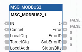
Parameter | Parameter Type | Data Type | Description |
|---|---|---|---|
IN | Input | BOOL | Rung input state.
|
Cancel | Input | BOOL |
Cancel input is dominant. |
LocalCfg | Input | MODBUS2LOCPARA | Defines structure input (local device). Define the input structure for the local device using the MODBUS2LOCPARA data type. |
TargetCfg | Input | MODBUS2TARPARA | Defines structure input (target device). Define the input structure for the target device using the MODBUS2TARPARA data type. |
LocalAddr | Input | MODBUSLOCADDR | MODBUSLOCADDR data type is a 125 Word array. LocalAddr usage:
|
Q | Output | BOOL | Outputs of this instruction are updated asynchronously from the program scan. Output Q cannot be used to re-trigger the instruction because IN is edge triggered.
|
Error | Output | BOOL | Indicates an error detected.
|
ErrorID | Output | UINT | A unique numeric that identifies the error. The errors for this instruction are defined in Modbus2 error codes. |
StatusBits | Output | UINT | Used to verify status bits:
Other bits are reserved. |
SuberrorID | Output | UINT | SubError code value when Error is TRUE. When an MSG is triggered, or re-triggered, a previously set SubErrorID is cleared. |
MSG_MODBUS2 examples
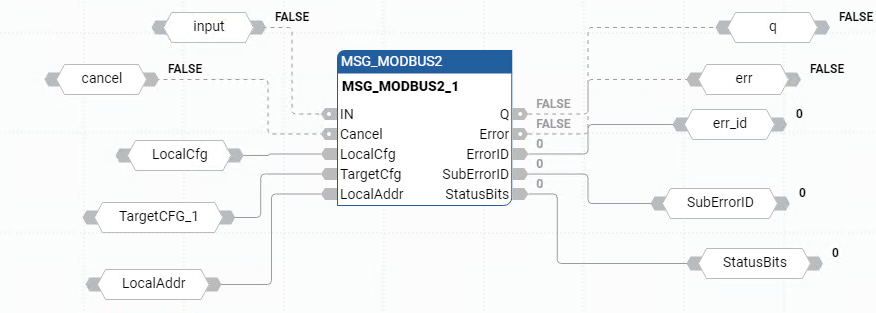
MSG_MODBUS2 function block diagram example
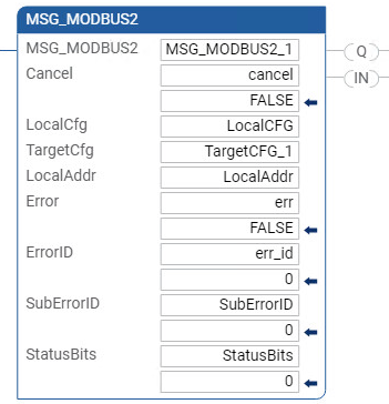
MSG_MODBUS2 ladder diagram program example
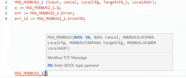
MSG_MODBUS2 structured text program example
Provide Feedback