I/O Connections
If communication with a device in the I/O configuration of the controller does not occur in an application-specific period, the communication times out and the controller produces warnings.
The minimum timeout period that, once expired without communication, causes a timeout is 100 ms. The timeout period can be greater, depending on the RPI of the application. For example, if your application uses the default RPI = 20 ms, the timeout period is 160 ms.
When a timeout does occur, the controller produces these warnings;
- I/O Fault status information scrolls across the 4-character status display of the controller.
- An exclamation point shows over the I/O configuration folder and over the devices that have timed out.
- A module fault code is produced, which you can access via the following:
- The Module Properties dialog box
- A GSV instruction
For more information about I/O faults, see the Logix 5000 Controllers Major, Minor, and I/O Faults Programming Manual, publication 1756-PM014.
I/O Communication Timeout
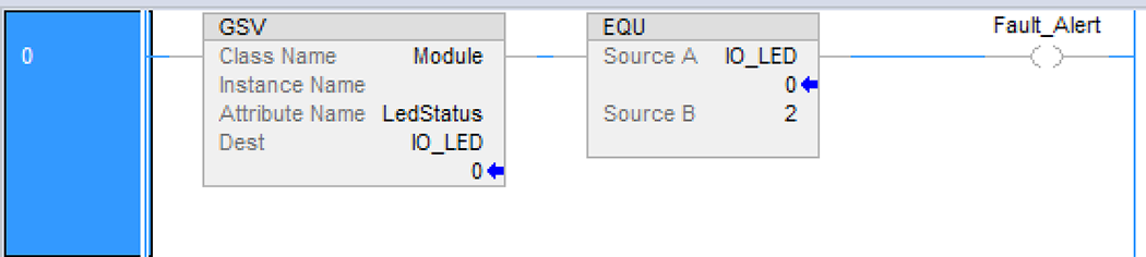
You can use this example to help determine if controller communication has timed out:
- The GSV instruction gets the status of the I/O status indicator (via the LEDStatus attribute of the Module object) and stores it in the IO_LED tag.
- IO_LED is a DINT tag that stores the status of the I/O status indicator or status display on the front of the controller.
- If IO_LED equals 2, then at least one I/O connection has been lost and the Fault_Alert is set.
GSV Used to Identify I/O Timeout
IMPORTANT:
Safety Consideration
Safety controllers have individual connection status on each safety I/O module as part of the input tag.
I/O Communication to a Specific I/O Module Time Out
If communication times out with a device (module) in the I/O configuration of the controller, the controller produces a fault code and fault information for the module. You can use GSV instructions to get fault code and information via the FaultCode and FaultInfo attributes of the Module object.
I/O Module Connection Faults
Depending on your application, you may want an I/O connection error to cause the Controller Fault Handler to execute. To do so, set the module property that causes a major fault to result from an I/O connection error. The major fault causes the execution of the Controller Fault Handler.
ATTENTION:
You cannot program Safety I/O module connections or safety produce/consume connections to automatically cause a major fault on the controller.
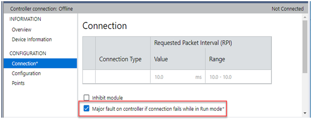
If it is important to interrupt your normal program scan to handle an I/O connection fault, set the ‘Major Fault On Controller If Connection Fails While In Run Mode’ and put the logic in the Controller Fault Handler.
I/O Connection Fault Causes Major Fault
If responding to a failed I/O module connection can wait until the next program scan, put the logic in a normal routine and use the GSV technique that is described on page 140 to call the logic.
First, develop a routine in the Controller Fault Handler that can respond to I/O connection faults. Then, in the Module Properties dialog box of the I/O module or parent communication module, check 'Major Fault On Controller If Connection Fails While in Run Mode.
It takes at least 100 milliseconds to detect an I/O connection loss, even if the Controller Fault Handler is used.
For more information about programming the Controller Fault Handler, see the Logix 5000 Major, Minor, and I/O Faults Programming Manual, publication1756-PM014.
Provide Feedback