PWM (pulse width modulation)
The PWM instruction turns the PWM output for a configured PWM channel ON or OFF.
This instruction block is used with L20E controllers and supports one PWM channel using the embedded output channel 6.
Languages supported: Function block diagram, ladder diagram, structured text.
This instruction applies to the L20E controllers.
PWM
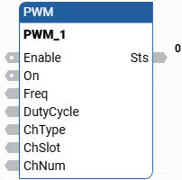
PWM
Parameter | Parameter Type | Data Type | Description |
|---|---|---|---|
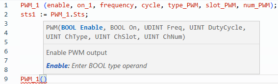
Enable | Input | BOOL | Instruction block enable. This level is instruction block triggered.
|
On | Input | BOOL | Turns the PWM output ON/Active or OFF/Inactive.
|
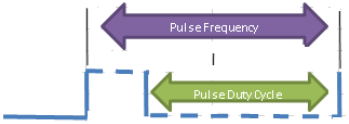
Freq | Input | UDINT | Pulse Frequency.
|
DutyCycle | Input | UINT | Pulse Duty Cycle.
|
ChType | Input | UINT | Channel Type.
|
ChSlot | Input | UINT | Channel Slot.
|
ChNum | Input | UINT | Channel Number.
|
ENO | Output | BOOL | Enable output. Applies only to ladder diagram programs. |
Sts | Output | UINT | PWM status codes:
|
PWM examples
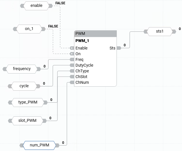
PWM function block diagram example
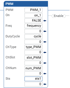
PWM ladder diagram example
PWM structured text example
Provide Feedback