Example: Add a Programmable Limit Switch function
This example explains how to add a Programmable Limit Switch (PLS) function to the HSC program.
Variable values for the counter settings
- MyAppData.PlsEnable is used to enable or disable the PLS settings. It should be set to FALSE (disabled) if the MyAppData variable is used.
- MyAppData.HscID is used to specify which embedded inputs will be used based on the mode and application type. See HSC Inputs and Wiring Mapping to know the different IDs that can be used as well as the embedded inputs and its characteristics.
- If ID 0 is used, ID 1 cannot be used on the same controller because the inputs are used by Reset and Hold.
- MyAppData.HscMode is used to specify the type of operation the HSC uses to count. See HSC Mode (HSCAPP.HSCMode).
To enable PLS
- InProject Organizer, under your HSC program, double-clickLocal Variables.
- In theInitial Valuecell of the MyAppData.PlsEnable variable, selectTrue.
- Configure the underflow and overflow settings.
- In theInitial Valuecell of MyAppData.OFSetting, enter50.
- In theInitial Valuecell of MyAppData.UFSetting, enter–50.
- (optional) Configure the output mask of an output.Results for this example:
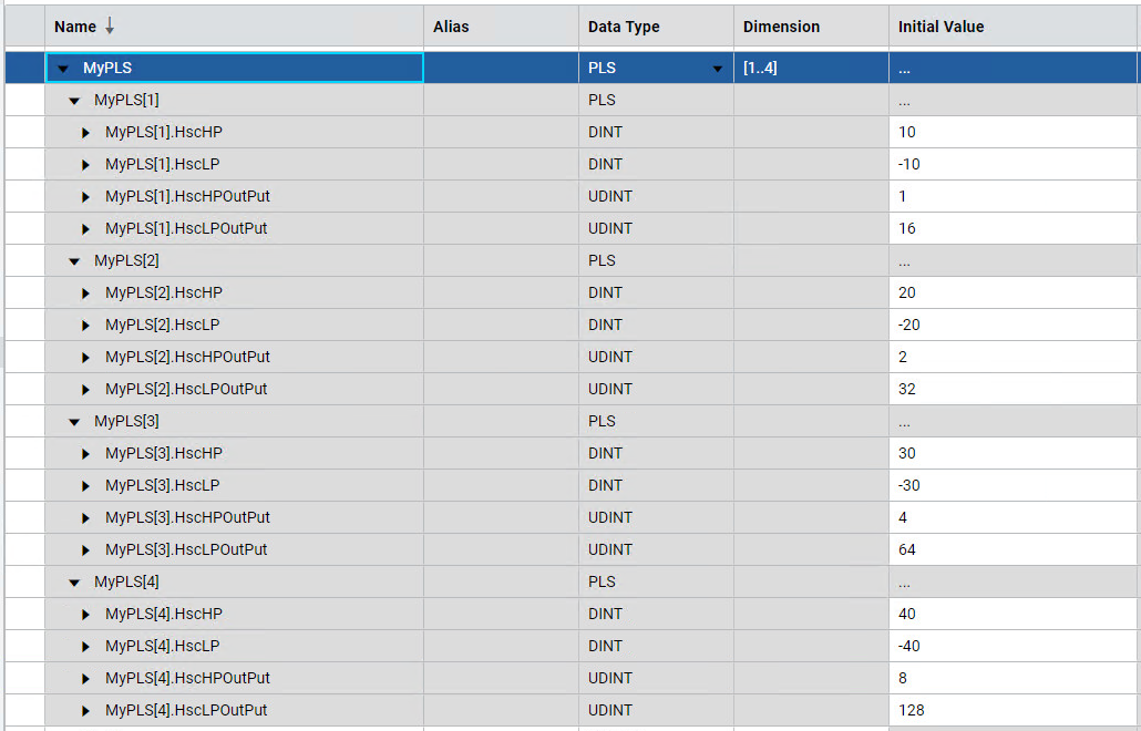
- The PLS variable has a dimension of [1..4]. This means that HSC can have four pairs of High and Low Presets.
- High Preset values must be lower than the OFSetting and the Low Preset must be greater than the UFSetting.
- The HscHPOutPut and HscLPOutPut values determine which outputs are turned on when a High Preset or Low Preset is reached.
Provide Feedback