
Add Alarms and Events to a FactoryTalk Optix Connector
Users can add the alarms and events to the
FactoryTalk Optix
connector. Alarms are typically used to indicate the conditions that need immediate attention. An alarm is activated when a defined threshold or condition is reached, such as a temperature exceeding a specified limit. To add an alarm to the connector, the user should create an alarm object, configure its properties, and set up a display widget like the alarm grid. For more information, refer to Alarms in the FactoryTalk Optix
documentation.Events are used to track both critical and non-critical system changes and activities. For more information on how to add events, refer to Events in the
FactoryTalk Optix
documentation.
NOTE:
Events are generated whenever there is a change in the alarm state from True to False.
The Exclusive Level Alarm monitors the values of variables related to physical quantities. This alarm is activated when the value of the monitored variable reaches one or more specified limits. If multiple limits are reached consecutively, the alarm signals only the last limit reached. This section describes how to bind the Exclusive Level Alarm to the connector.
NOTE:
The user can bind all other alarm types as well.
In the 1.07.00 release, the new (observable) pattern was implemented to streamline the process of pushing alarms and events. This enhancement eliminates the need for extensive manual configuration of the push alarm method and its associated parameters, making the process more efficient and user-friendly. The following section describes how to use it.
Configure an Exclusive Level Alarm grid by following the steps described in FactoryTalk Optix documentation and configure its Exclusive Level Alarm event with the following steps:
- Open theFactoryTalk Optixproject in theFactoryTalk Optix Studio.
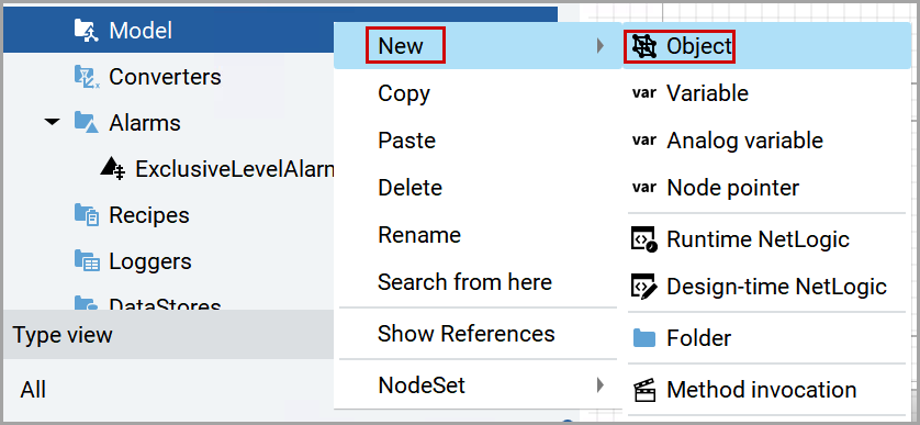
- From the left pane, right-click theModeland navigate toNew>Object.Select Object
 An object is created under the model.Created Object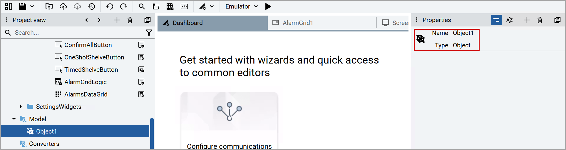
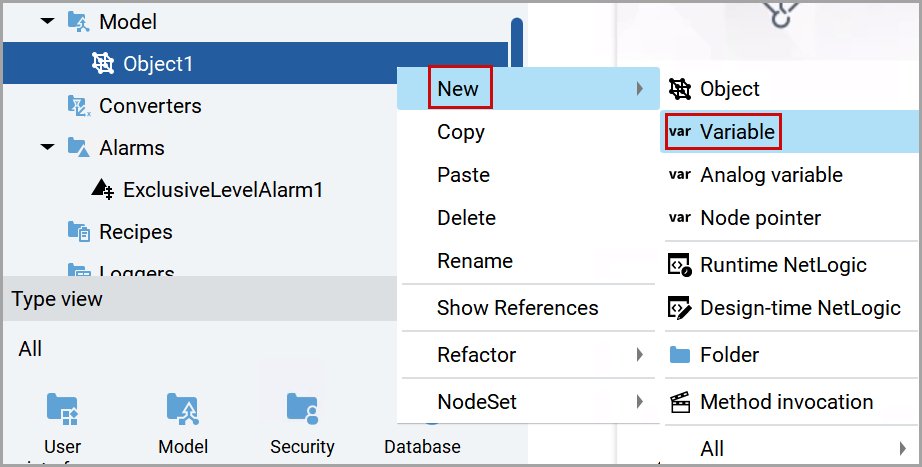
- Right-click the newly created object and navigate toNew>Variable.Select Variable
 The variable is created under the newly created object.Created Variable
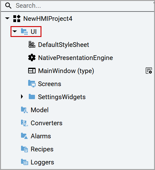
- From the left pane, expand theUInode.Expand UI Node
- Right-click theScreensobject and navigate toNew>Screen.Select Screen
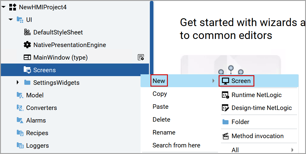 NOTE:If there is no Screens object, right-click on theUInode and navigate toNew>Screens.Select Screens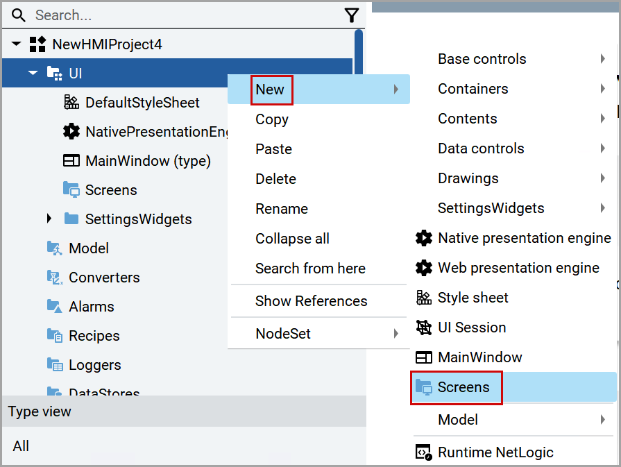
- Right-click theScreen1 (type)object and navigate toNew>Containers>Panel.Select Panel
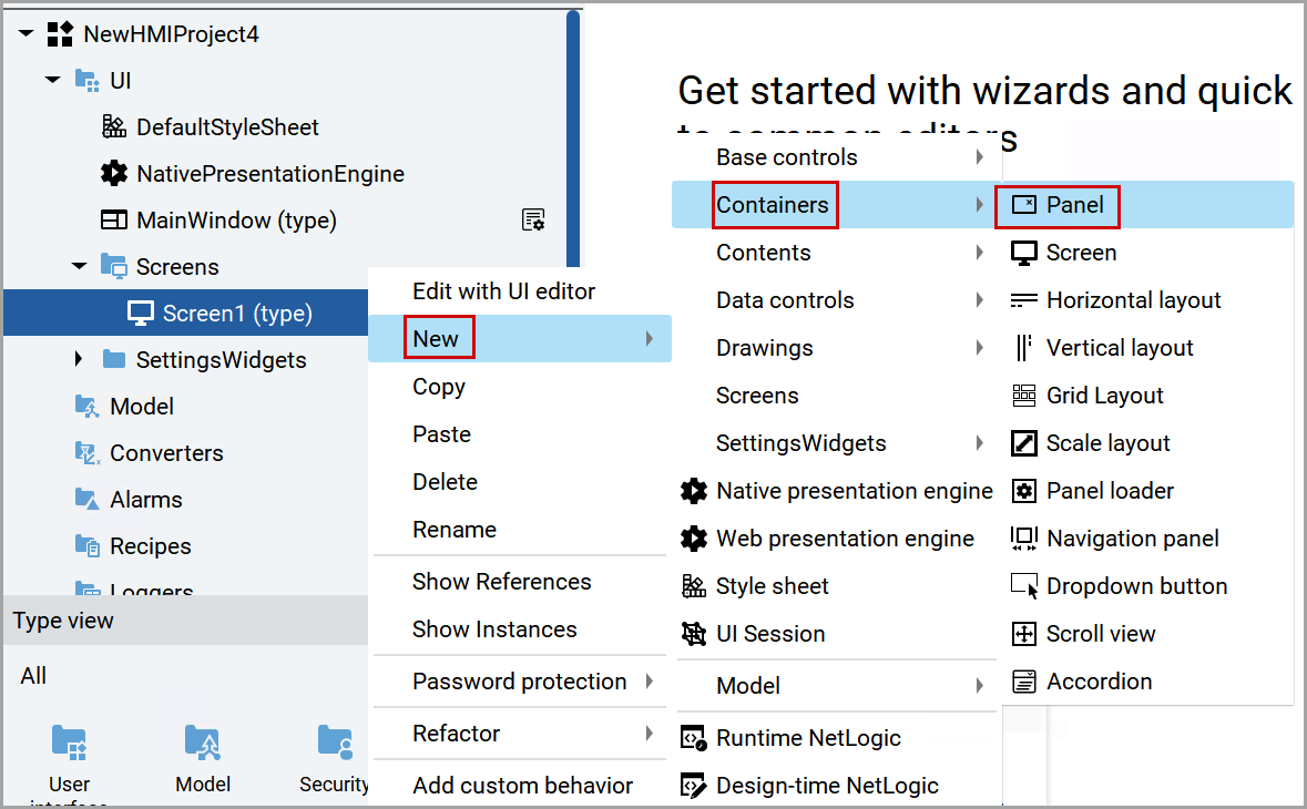
- Hover over the newly created panel name and click the [
 ] icon to rename the panel name. For example, “Alarms”.Rename Panel Name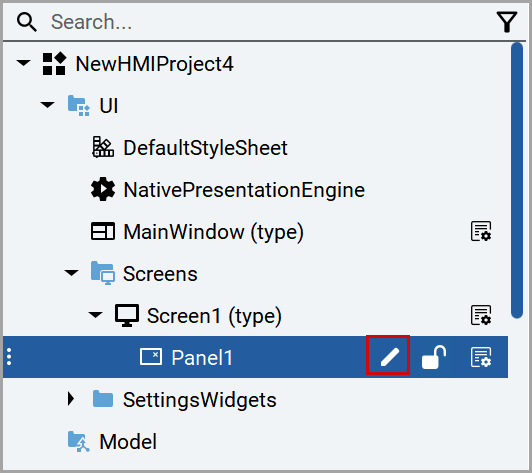
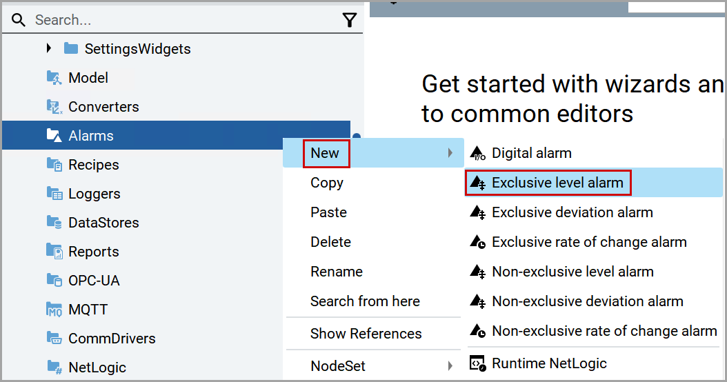
- From the left pane, right-click theAlarmsand navigate toNew>Exclusive level alarm.Select Exclusive Level Alarm
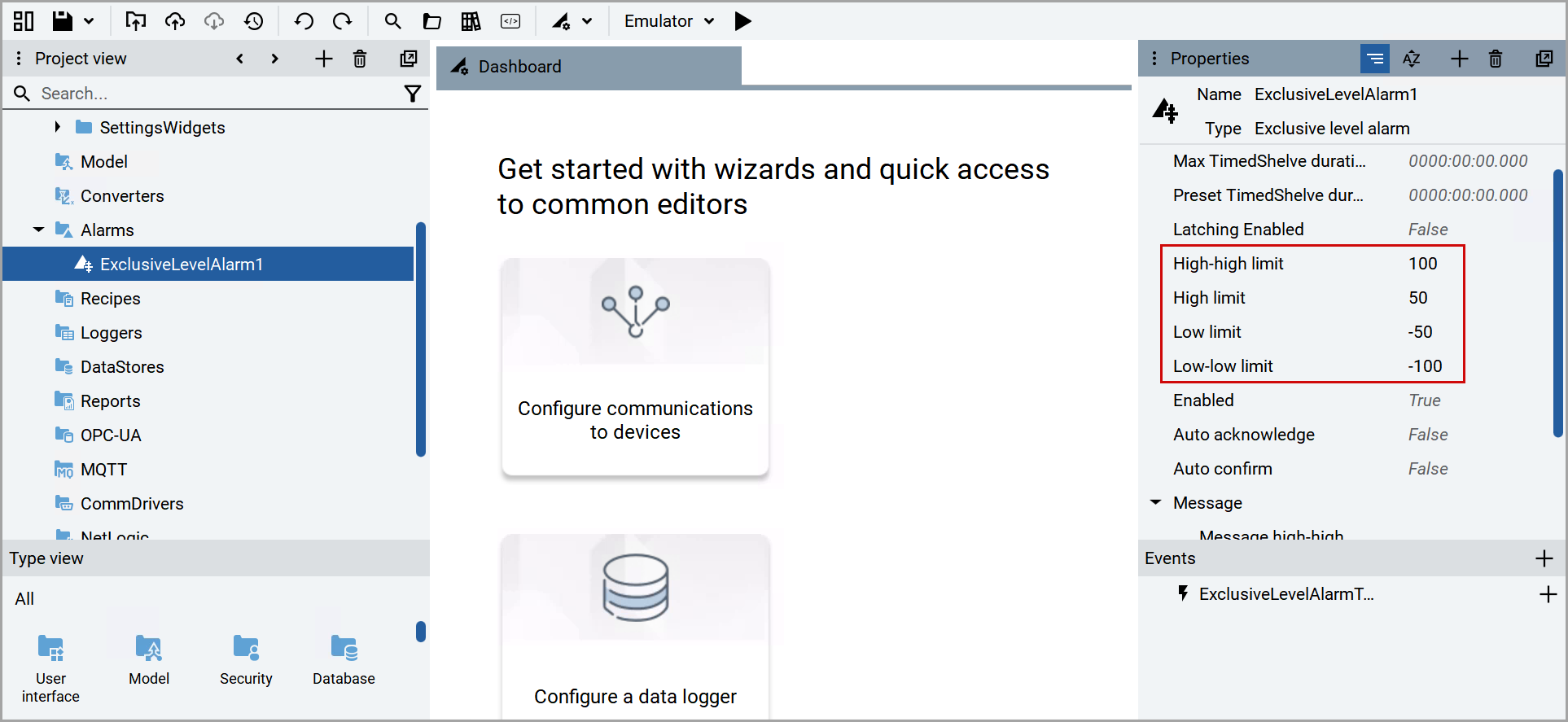
- In thePropertieswindow, Provide the limit values for theHigh-high limit,High limit,Low limit, andLow-low limit.Set Limits
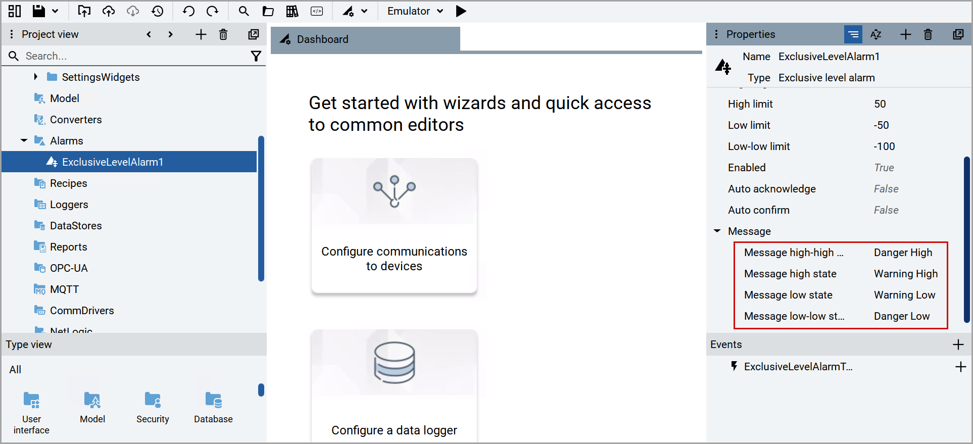
- Under theMessagessection, provide the appropriate alarm message for thehigh-high state,high state,low state, andlow-low state.NOTE:This message will be added as a description in the event in Cognite.Add Alarm Messages
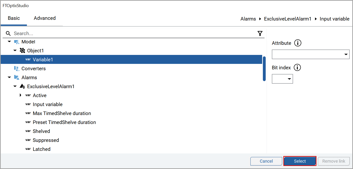
- In theInput variablebox, Click the [
 ] icon.Add Dynamic Link
- In theFTOptixStudiowindow, select the newly created variable and clickSelect.FactoryTalk Optix Studio Window
- Click the [
 ] from the top menu.Click Libraries Icon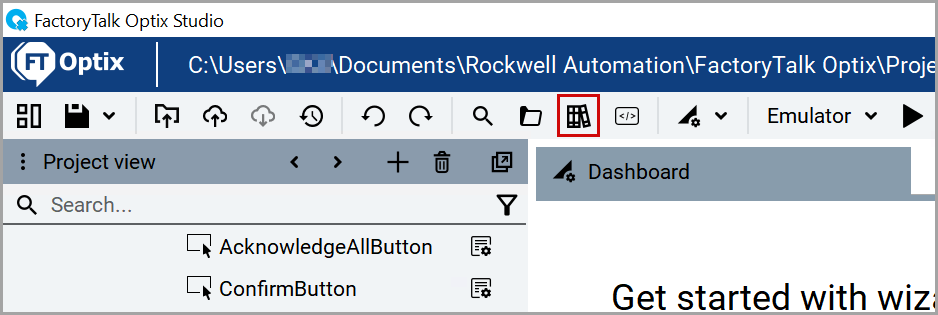
- In theLibrarieswindow, clickWidgets.
- UnderComponents, drag theAlarm Gridand drop under theAlarmspanel in the left pane.Add Alarm Grid
 TheAlarmGrid1is added underAlarms.AlarmGrid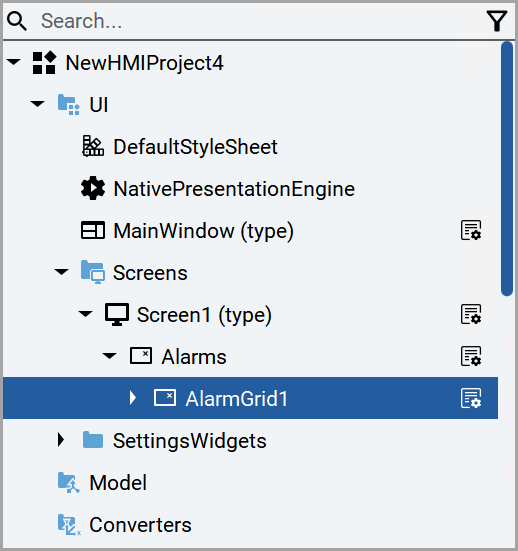
- Close theLibrarieswindow.
- Expand the newly created alarm grid and clickAlarmsDataGrid.
- In thePropertieswindow, click the [+] icon next to theColumnsand clickText column.Add Text Column
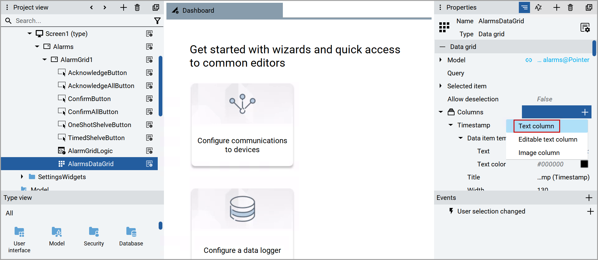
- Scroll down thePropertieswindow to view theDataGridColumn1.
- In theTextbox, click the [] icon.Click Dynamic Link
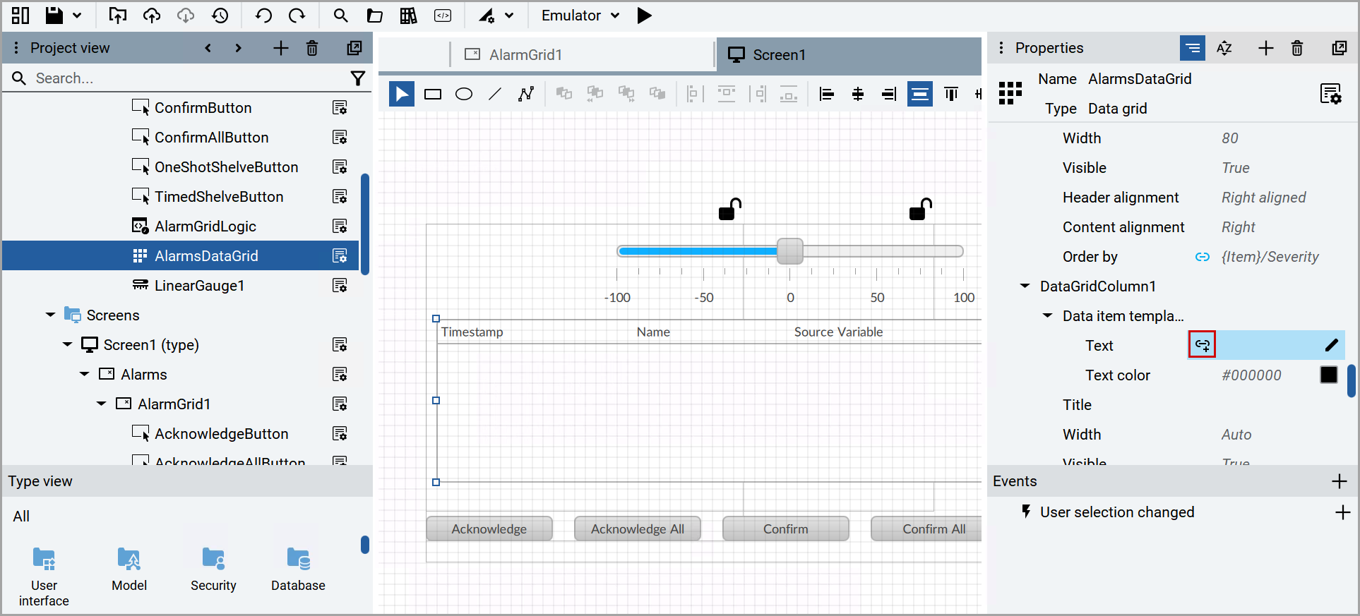
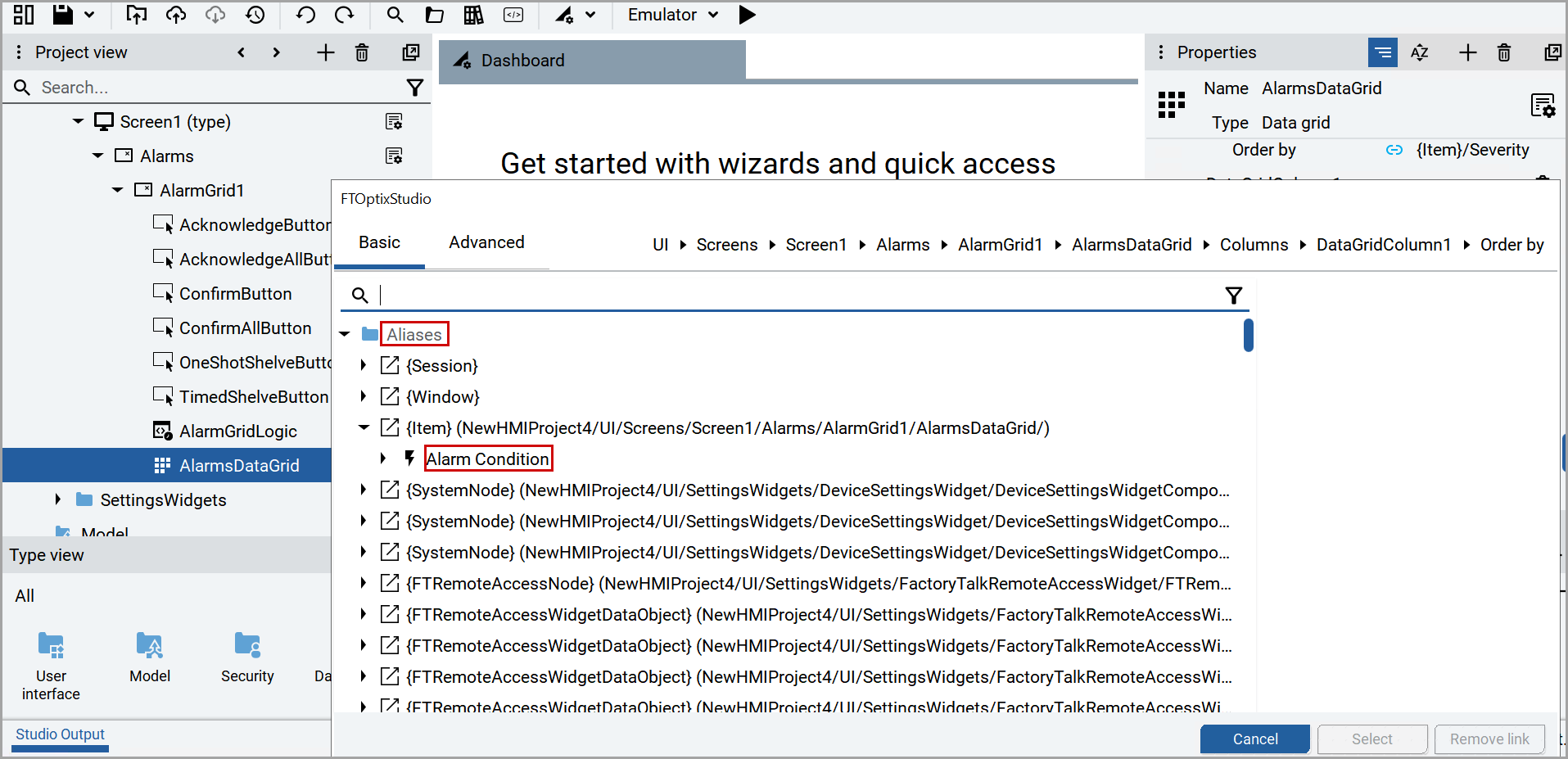
- In theFTOptixStudiowindow, under theBasictab, expandAliases.
- ExpandAlarms DataGrid.
- ExpandAlarm Condition.Expand Alarm Condition
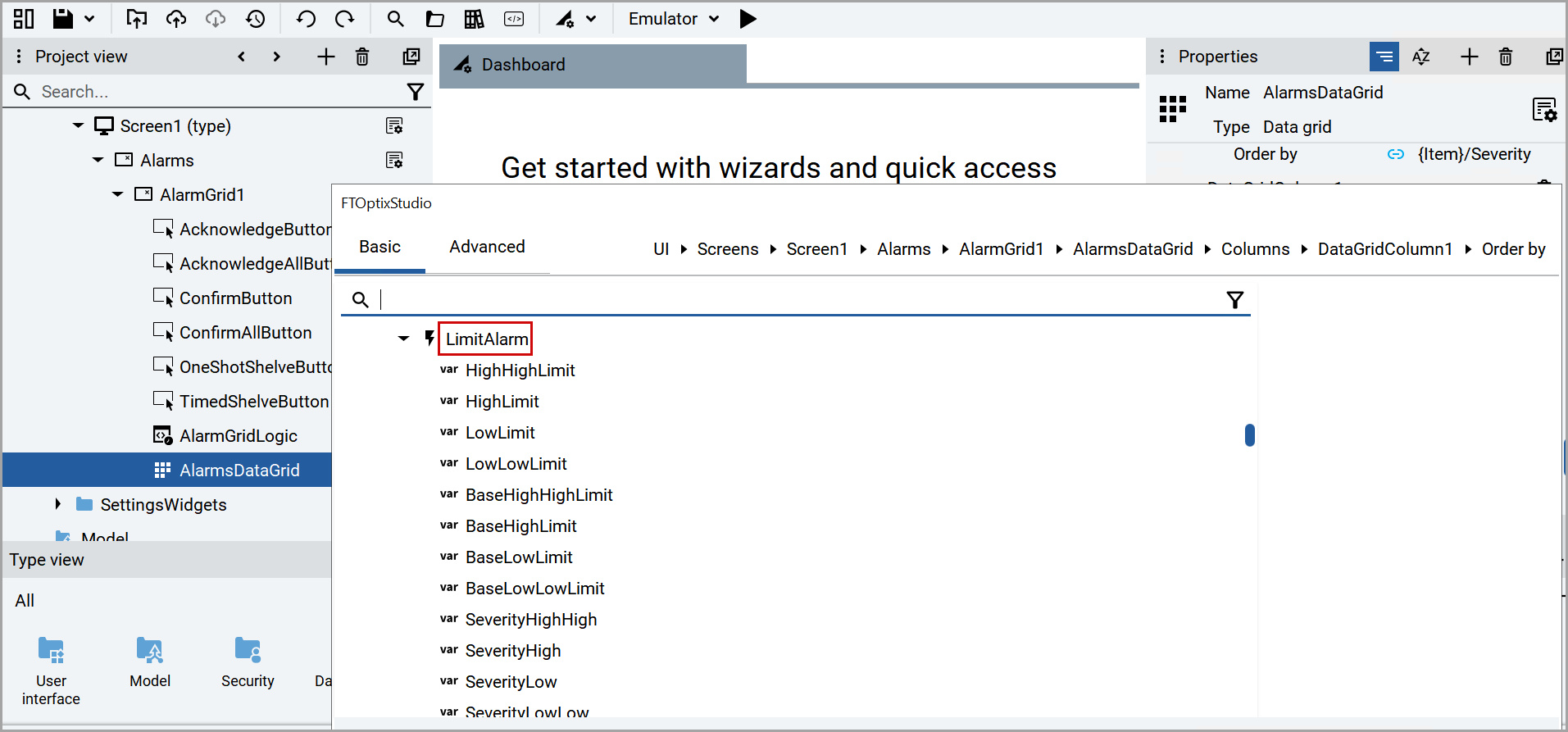
- Scroll down and expandLimit Alarm.Expand Limit Alarm
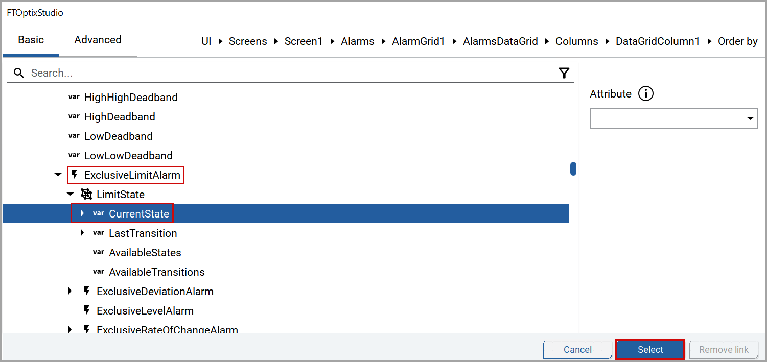
- ExpandExclusiveLimitAlarmand selectCurrentState.
- ClickSelect.FactoryTalk Optix Studio Window
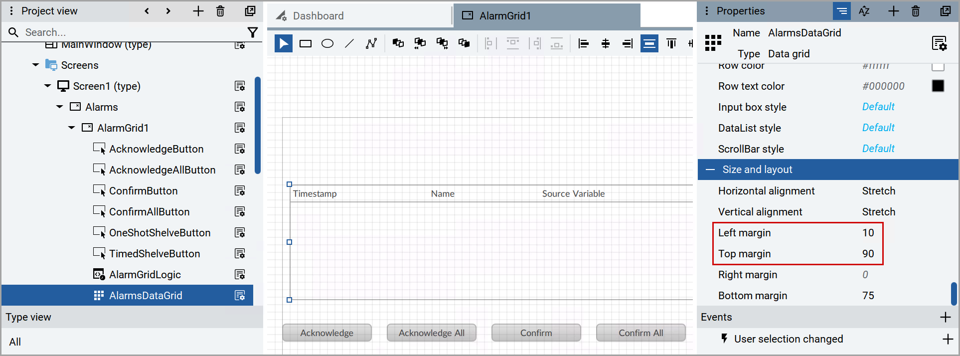
- Click theAlarmDataGridfrom the left pane.
- In thePropertieswindow, provide theLeft MarginandRight Marginvalues as per your screen resolution.Set Margins
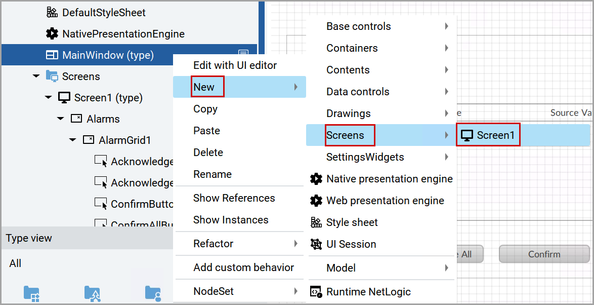
- Right-click theMainWindow (type)and navigate toNew>Screens>Screen1to add the newly created screen to the main window.Add Screen
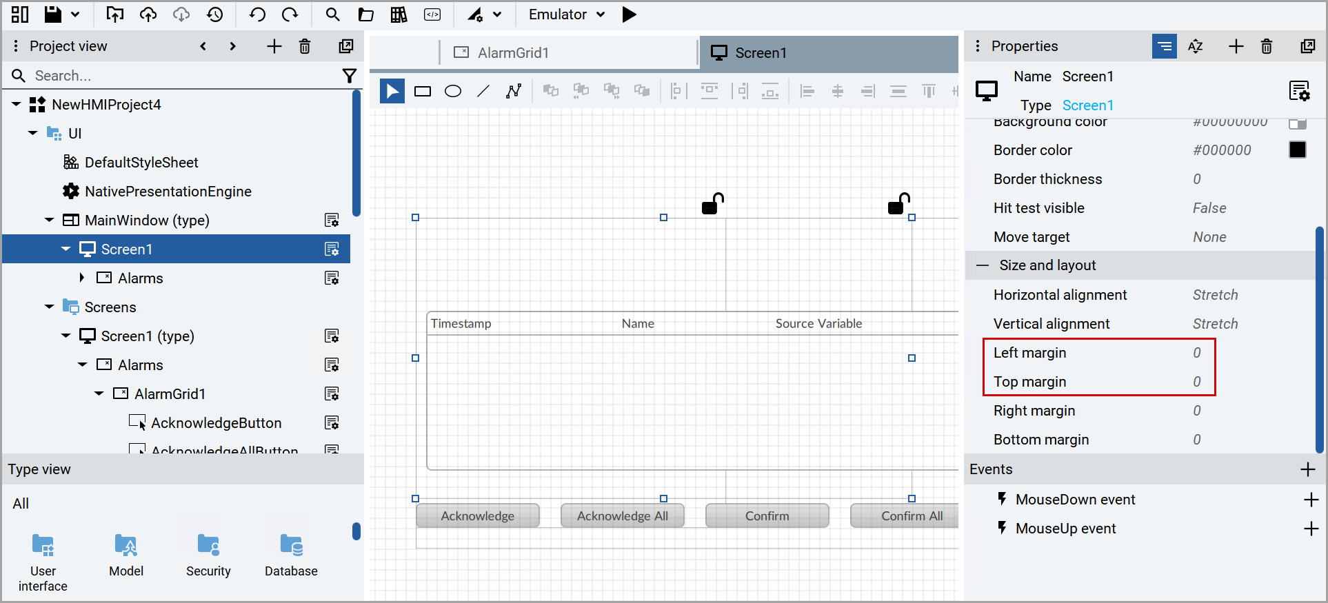
- In thePropertieswindow, set the Left and Right margin values as zero.Set Margins
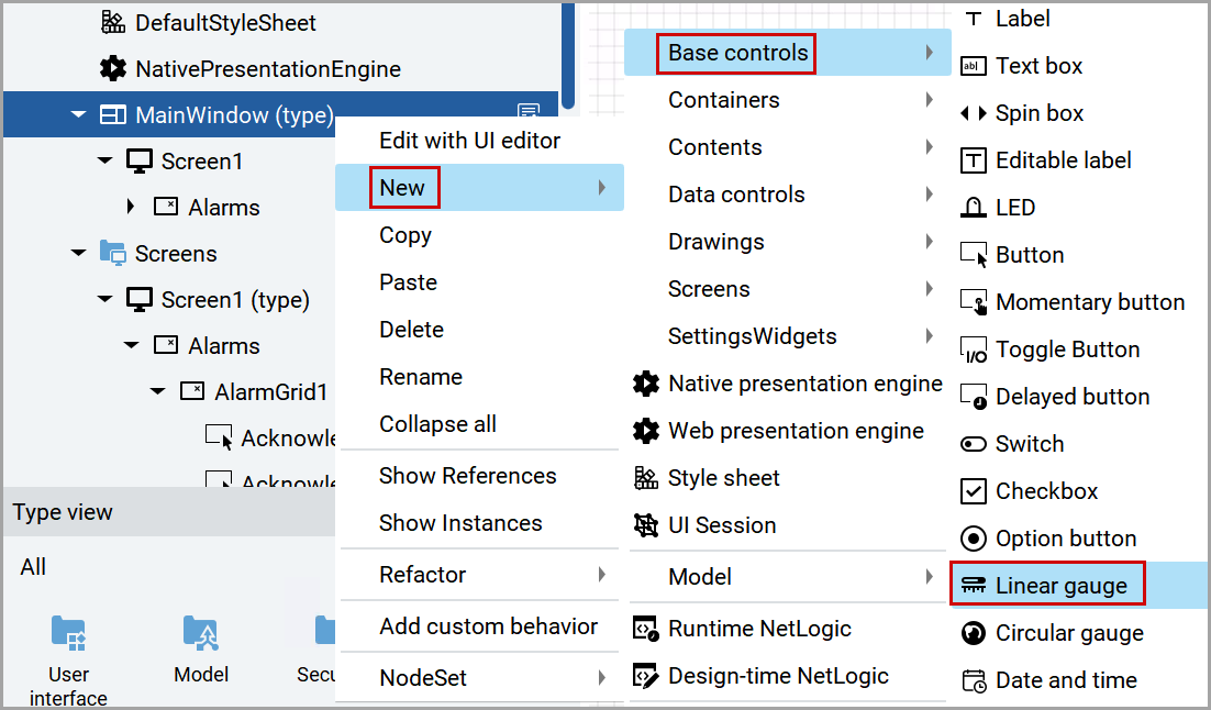
- Right-click theMainWindow (type)and navigate toNew>Base controls>Linear gauge.Add Linear Gauge
- Drag the newly created linear gauge in the UI editor (Screen1) to just above theAlarmGrid.Linear Gauge
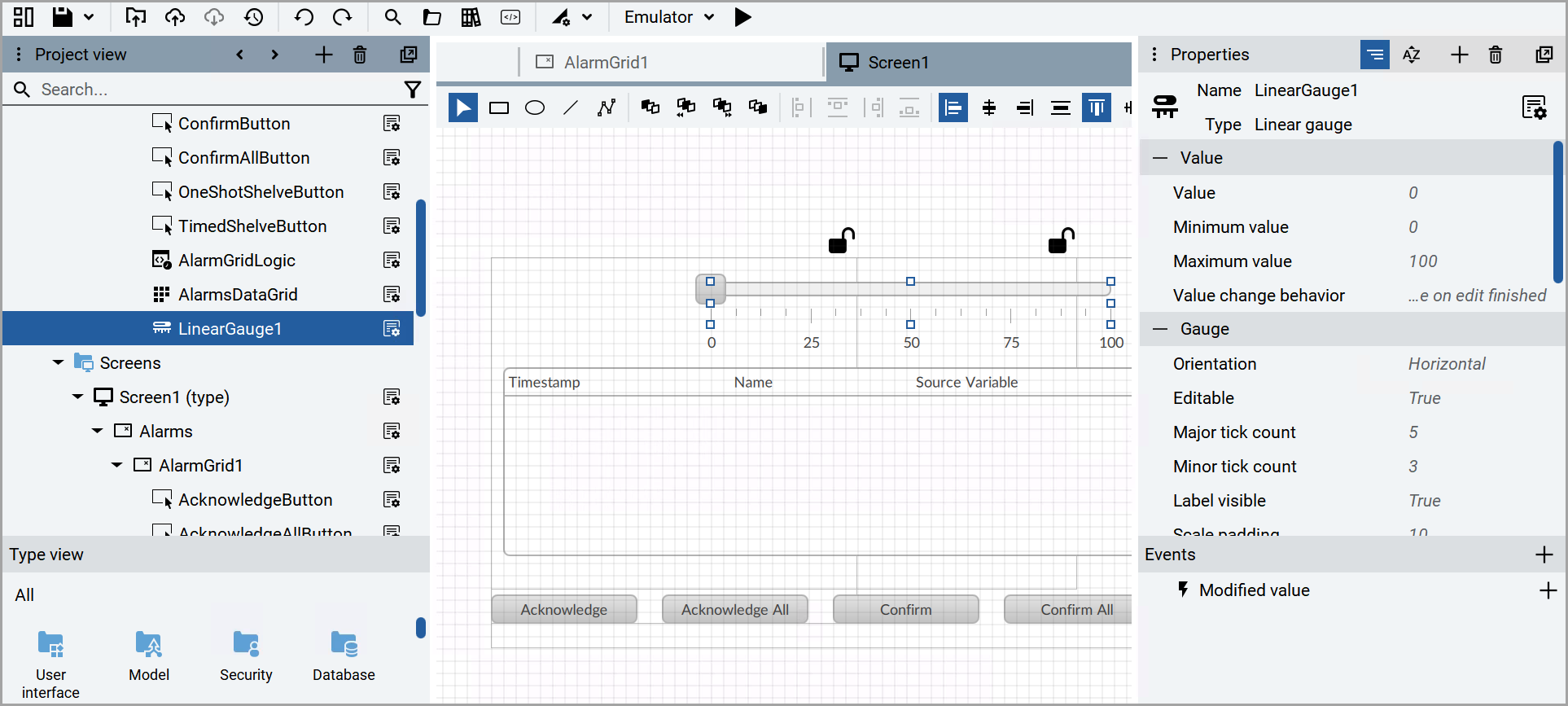
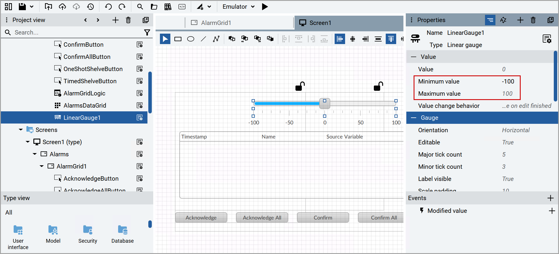
- Select theLinearGauge1from the left pane.
- In thePropertieswindow, set the Minimum and Maximum values.Set Limits
- Click the [] icon from the Valuebox.Add Dynamic Link
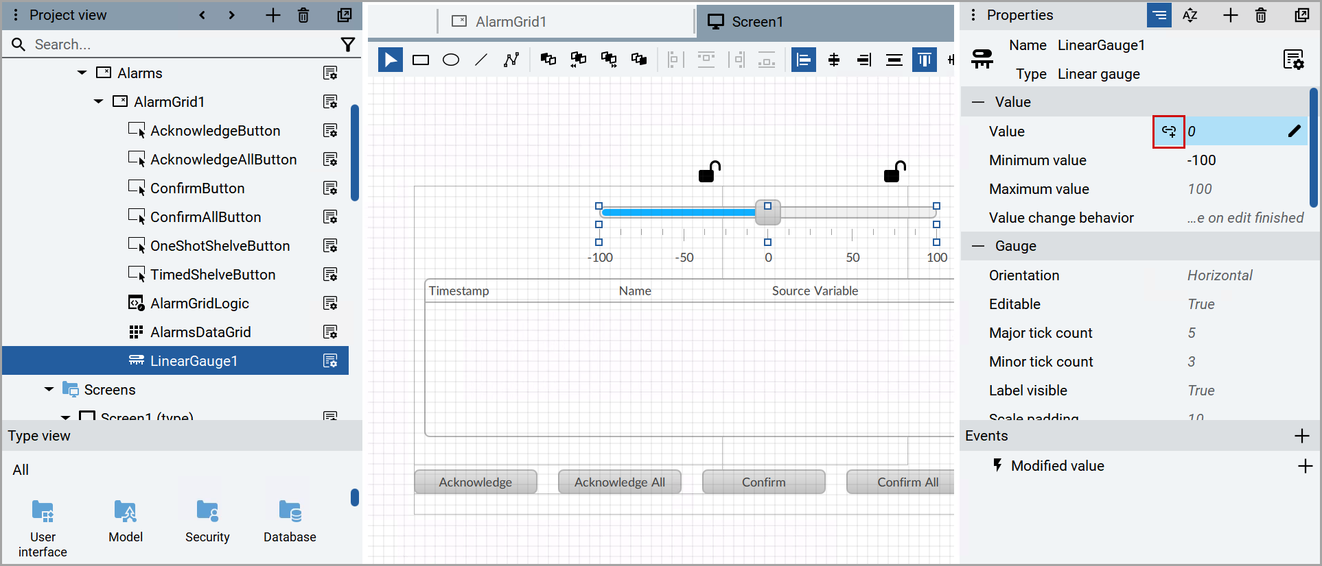
- In theFTOptixStudiodialog box, select the newly created variable and clickSelect.FTOptixStudio WindowNOTE:To adjust the size of the main window, double-click theMainWindow (type)node under theUInode, then drag the edges of the selected window object in the UI editor (Screen1).
- Configure other objects in your project (such as the FTDataMosaixDataStore object).
- Click the [
 ] icon to run the emulator.
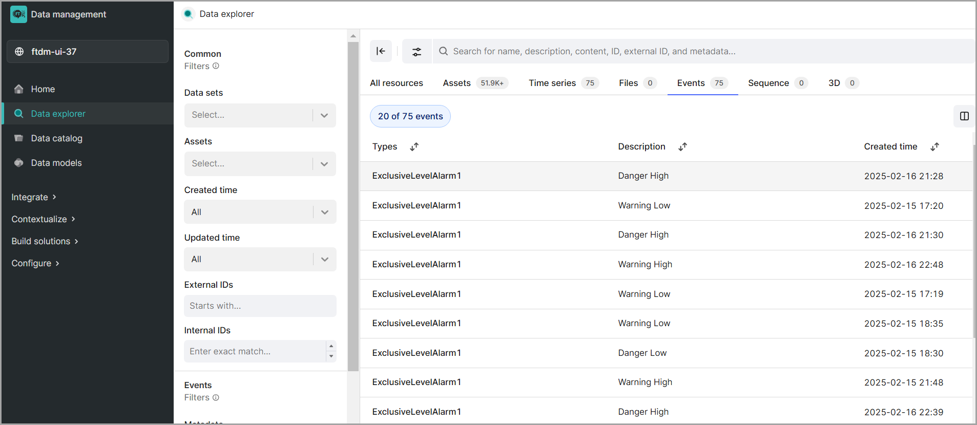
 - Generate an alarm by adjusting the configured variable's value using the linear gauge to set it within the High, High-high, Low, or Low-low threshold limits. This action will trigger an alarm that is displayed in the Alarm Grid. When the value returns to a normal state via the linear gauge, an event is created and pushed to Cognite, accessible under the Data Explorer menu in the Events tab.Alarm State Change
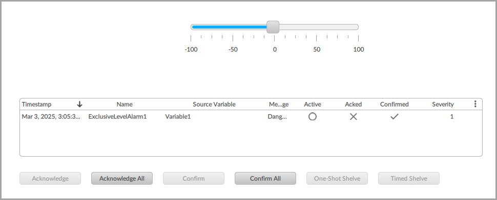 Alarm State Change
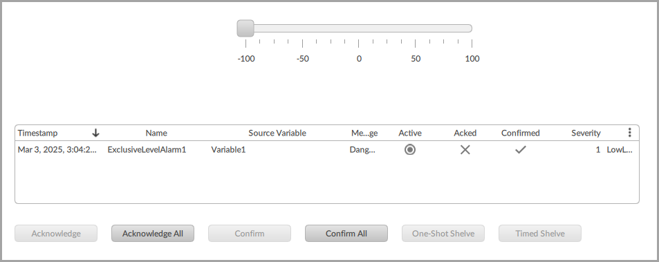 NOTE:The user can clickAcknowledge Alland thenConfirm Allto acknowledge and confirm the events. The events will not be generated if the user acknowledge or confirm the events.Open the Cognite page to view the alarm details.Alarm Details - Cognite
 The user can view the configured description when pushing events to Cognite.Exclusive Alarm Details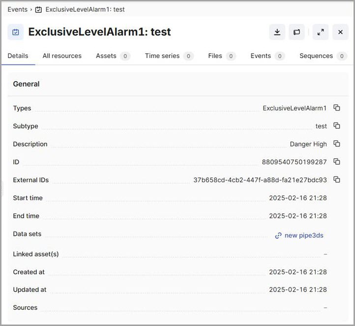
Provide Feedback