
1734sc-IE2/4CH Module Configuration
Use this tab to configure the Spectrum Controls 1734sc-IE2/4CH HART analog input module.
On this tab, you can:
- select a module notch filter
- enter an update rate period
- enter a pass through hold time
Tip
: The module’s configuration information is stored in the controller and the controller configures the module.Note
: The 1734sc-IE2/4CH Owner’s Guide, which is available online by following the hyperlink on the Vendor tab, provides additional configuration information for some of the parameters discussed in this help file.Notch Filter
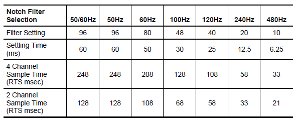
Select an ADC filter cutoff frequency for all inputs. The module filter is a built-in feature of the Analog-to-Digital converter which attenuates the input signal beginning at the specified frequency. Selecting a low value (i.e. 50 Hz) for the filter frequency provides the best noise rejection for a channel, but it also increases the channel update time. The module update time is defined as the time required for the module to sample and convert the input signals of all enabled input channels and make the resulting data values available to the processor. The update time is influenced by the input type and filter frequency configuration settings.
In addition to frequency rejection, a by-product of the filter selection is the minimum sample rate (RTS) that is available. For example, the 100Hz selection will not attenuate any frequencies less than 100Hz and will allow sampling of all 4 channels within 128ms. But the 50Hz selection will reject all frequencies above 50Hz and will only allow sampling all 4 channels within 248ms. The table above lists the minimum RTS rate associated with each ADC filter setting.
Update Rate (Sample Period)
Enter the time (in milliseconds) to indicate how often the module’s inputs are to be sampled (refer to table above for minimum allowed). The period controls how often the module prepares new readings. There is only one RTS for the entire module. The Requested Packet Interval (RPI on the Connection tab; range 10ms to 750ms) controls how often the module sends its current readings to the controller. In a local chassis, the RPI is generally set faster than the Update Rate to ensure each new sample is sent to the controller at least once. In a remote chassis, the RPI and RTS may also need to be set relative to the Network Update Time.
HART Pass Through Hold Time
Enter a Hold Time value for the final reply of the pass-through message.
After the module obtains the requested information from the HART device, it will start the Hold Timeout timer (duration defined by the HoldTime tag). The reply message will be kept in memory during the Hold Time period. After the timeout occurs, or after the message is retrieved by the pass-through response query command, the storage buffer will be discarded and another pass through message will be serviced without being rejected. Hold Time is in the range of 0 to 255 seconds.
OK
Click this button to accept your edits on any tab and close the dialog.
Cancel
Click this button to cancel your edits on any tab and close the dialog.
Apply
Click this button to apply your edits on any tab and continue editing.
If:
- you are online in Program, Remote Program or Remote Run mode and,
- this controller is the owner controller and,
- you have changed the module’s configuration in the software, when you click the Apply or the OK button, the information is automatically sent to the controller. The controller tries to send the information to the module (if the module’s connection is not inhibited). If you don’t click Apply, your changes are not sent to the controller.
Help
Click this button for help on this tab.
Related Topics
- Reconfigure an I/O Module Programmatically - refer to RSLogix5000 HELP
- Reset Latched Status on an Analog Module - refer to RSLogix5000 HELP
Provide Feedback