
General
Function
The Spectrum Controls’ 1756sc-CTR8 is a Counter/Flowmeter module for use with ControlLogix controllers in the 1756 system.
- Eight uni-directional 24-bit counters
- Paired channels support up to four bi-directional counters or quadrature encoders (x1 or x4)
- Simultaneous rate measurement in all modes.
- User-programmable roll-over/under, stop on limit
- Mix DC counter, AC flowmeter inputs. AC suitable for VRC flowmeter inputs.
- Turbine flowmeter inputs can include scaling factors and support meter-proving.
- Update Time <13 ms for all channels
- Selectable signal mismatch and out-of-range detection
- Timestamping of produced data
Field Interface
- Selectable input types: 5, 12/24 V dc, 50mV ac, 200mV ac (input types configured in channel pairs)
- Input frequency: 0 to 65 KHz. Pulse time 5.4 µs min.
- Gate input signal to control counter operation.
- Selectable input filters
- Over-voltage and over-current protection for specific conditions.
- Field connector and cables:
- Standard 36-pin removable terminal block; 1756-TBCH (screw) or 1756-TBS6H (press); ordered from Rockwell Automation; RTB mechanical keying.
- Refer to the module’s "Owner’s Guide” for recommended shielded twisted-pair cable, a list of standard pre-wired cables, and complete wiring recommendations and considerations.
Module Identity
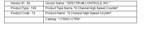
The module Identity includes the following Device attributes (refer to "EDS File” below):
Data
The following module data types and tags are created by the AOP:
- Input Tag (120 bytes)
- Channel analog values, count and rate.
- Channel Status and Fault Words. Module Fault Word.
- Timestamp
- Output Tag - (8 bytes)
- Counter control
- Miscellaneous enables and resets
- Configuration Tag (216 bytes) - configurable through the AOP configuration tabs.
Note
: IO Tags are updated by the controller asynchronous to its ladder-logic program scan. When "block integrity” of this data is important, the CPS ladder instruction can synchronously copy the data to other tags for use by application logic. Refer to the "Owner’s Guide” for recommended methods.Communication
1756 Backplane Communication
- Connected producer/consumer multicast IO communication
- RPI = 10ms default, 10-750ms range
- Support for multiple controllers, either "listen only” or multiple owners.
- Local chassis operation, or Remote chassis operation (over CIP network).
- Unconnected messaging from controller (MSG instruction) or from a CIP network client.
- Reset or Reconfigure the module
- Unlatch alarms
Note
: Refer to detailed protocols and MSG examples described in the module’s "Owner’s Guide”, and examples in the module’s RSLogix5000 Sample Projects.Bus Power
From the 1756 backplane: 230mA at 5VDC, and 75mA at 24VDC.
Provide Feedback