
Motion Coordinate System
In the Logix Designer application, a coordinate system is a grouping of one or more primary or ancillary axes created to generate coordinated motion. The Logix Designer application supports these geometry types.
- Cartesian
- Articulated Dependant
- Articulated Independent
- Selective Compliant Assembly Robot Arm (SCARA) Independent
- Delta
- SCARA Delta
These are coordinate system examples.
Coordinate system with orthogonal axes
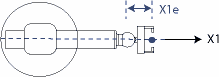 | 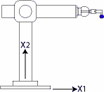 | 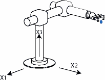 |
Cartesian coordinate system | Two-dimensional Cartesian coordinate system | Three-dimensional Cartesian coordinate system |
Coordinate systems with non-orthogonal axes
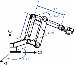 | 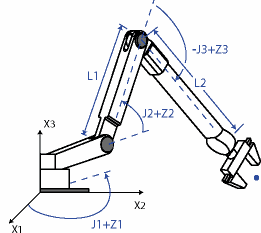 | 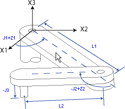 |
Articulated Dependent coordinate system | Articulated Independent coordinate system | SCARA Independent coordinate system |
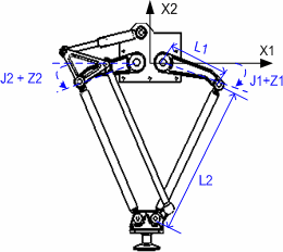 | 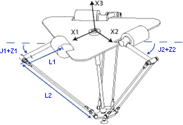 | 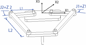 |
Delta Two-dimensional coordinate system | Delta Three-dimensional coordinate system | SCARA Delta coordinate system |
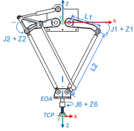 | 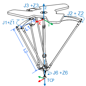 | 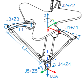 |
Delta J1J2J6 coordinate system | Delta J1J2J3J6 coordinate system | Delta J1J2J3J4J5 coordinate system |
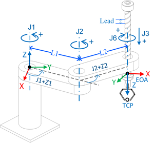 | ||
Scara Independent J1J2J3J6 |
Provide Feedback